|
6.1 -
|
|
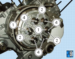
2
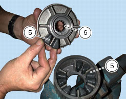
|
|
4
|
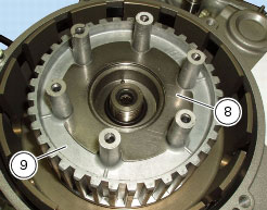
|
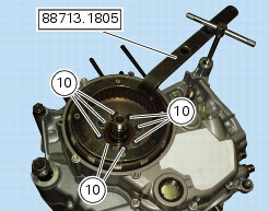
10
|
|
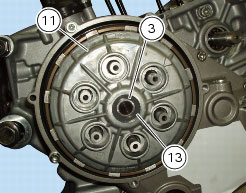
12
|
|
13
|
|
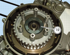
14
|
|
15
|
|
16
|
|
17
|
|
18
|
|
19
|
|
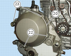
21
|
|
22
|
|
23
|


|
-
|
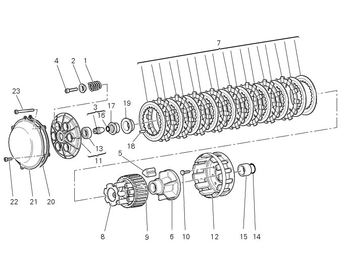
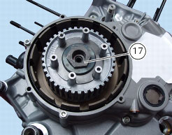
nut (17).
|

|
-
|
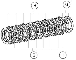
two plain plates (G) 1.5 mm thick;
|
|
-
|
one friction plate (H) 3 mm thick;
|