7 -
Instrument panel
Undo the screws (2) and remove the instrument panel shroud (1).
Disconnect the wiring (A) from the instrument panel (3).
Undo the screws (4) and remove the instrument panel (3) from the front lights assembly support.
When refitting, tighten the screws (2) and (4) to the specified torque (Sect. C 3, Frame torque settings).
Refitting is the reverse of removal; tighten the screws (4) to the specified torque (Sect. C 3, Frame torque settings).
Instrument panel system
The instrument panel comprises an LCD digital display unit.
The information on the display can be accessed using a 2-position rocker switch (1) and the headlight flasher button (2) on the left-hand handlebar switch.
Underneath the digital display there are six indicator lights (three per side) and a further auxiliary light that illuminates when the engine rpm exceeds the rev limiter threshold.
The instrument panel is equipped with a sensor that detects the intensity of the ambient light. The instrument panel automatically switches its backlighting on or off according to the intensity of light detected. The instrument panel also has an internal temper­ature sensor which, if the temperature rises above 70 °C, switches off the backlighting to prevent possible damage.
The instrument panel also houses the atmospheric pressure sensor: the engine ECU acquires this signal via the CAN (Controller Area Network) serial communication line.
Indicator lights
The following indicator lights are mounted on the instrument panel:
3) Neutral light N (green): illuminates when the gearbox is in neutral.
4) Fuel warning indicator (amber yellow): illuminates when there are approximately there are about 3 litres of fuel left in the tank.
5) Turn signal lights (green): illuminate and flash when the corresponding turn signal is in operation.
If a turn signal does not work (e.g. burnt out bulb) its incorrect operation is signalled by making the light flash twice as fast as in comparison to correct operation.
6) Engine oil pressure light (red): Illuminates when engine oil pressure is too low. This light should come on when the ignition is switched to ON and normally goes out a few seconds after engine starts. The case may occur that the light turns on briefly if the engine is very hot; it will turn off as the engine rpms increase.
7) High beam light (blue): illuminates when the high beam headlight is on.
8) “Engine/Vehicle diagnosis - EOBD” indicator (amber yellow): It turns on in the case of an engine or motorcycle error; in some cases the engine will be locked.
9) OVER REV. warning light: It comes on steady when the first rev limiter threshold (*) is reached. Starts flashing when the rev limiter is reached.
10) ABS LIGHT (AMBER YELLOW).
 
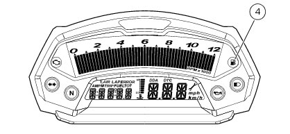
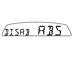
ABS disabled with the menu function “DISAB ABS” (*)
ABS disabled with the menu function “DISAB ABS”
ABS enabled and functioning
ABS disabled with the menu function “DISAB ABS”
ABS disabled and not function­ing due to a problem.
(*) depending on the model, each calibration of the Engine Control Unit may have a different “setting“ for the thresholds that precede the rev limiter and the rev limiter itself.
(**) The ABS should be considered actually disabled only if the light continues to flash after starting the engine.
Display settings and functions
On switching on the power (key turned from OFF to ON), the instrument panel activates all the digits of the LCD for 1 second and switches on all the warning lights in sequence.
It then reverts to “normal” mode and, in place of the odometer, shows the model and, for 2 seconds, also the version (EU, UK, USA, CND, FRA, JAP).
The model is scrolled on the display once only.
At Key-On, the instrument panel always shows the following information (de-activating any previously activated functions):
Odometer
Speed
Rpm bargraph
Engine oil temperature bargraph.
 
With the switch (1, fig. 8) in position B “t” the Odometer readout (TOT) will cycle through the following functions:
TRIP
TRIP FUEL (only if active)
Clock
before returning to Odometer display.
 
Pressing switch (1) in position A “s“ gives access to the MENU and the following functions are displayed one after another:
Error (only if active)
BATT
RPM
LIGHT SET
LAP (OFF or ON)
LAP MEM
DDA (OFF or ON)
Erase DDA
DISAB ABS
CLOCK SETTING
CODE (only if active)
Important
This menu is enabled only if the speed of the vehicle is less than 20 km/h. If this menu is on the display and the speed of the motorcycle exceeds 20 km/h, the instrument panel automatically exits the menu and returns to the initial display. It is possible to exit the menu at any time, however, by pressing switch (1) in position A “s” for 3 seconds.
Total distance travelled indicator (odometer)
At Key-On the system automatically enters this function.
The total distance travelled value is stored permanently in memory cannot be reset for any reason (except during the immobilizer first programming procedure when its reset to zero).
If it exceeds 99999 km (or 99999 miles), the reading “99999” remains displayed permanently.
“Speed” indicator
This function enables display of the motorcycle speed.
The instrument panel receives actual speed value (expressed in km/h) from the ECU and displays the value increased by 8%.
Maximum speed displayed is 299 km/h (186 mph).
Over 299 km/h (186 mph) the display will show a series of dashes “- - -“ (steadily lit - not flashing).
“TRIP“ meter
Holding button (1) pressed in position B “t“ for 3 seconds when this function is displayed resets the trip meter.
If the reading exceeds 999.9, it is reset to zero and the count restarts automatically.
If the System units of measurement are changed at any time with the “Setting Special” Function, the reading in this Function is reset and the count restarts from zero in the newly set unit of measurement.
“TRIP FUEL” (distance travelled on reserve fuel) indicator
When the fuel warning light (4) comes on, the TRIP FUEL meter is activated automatically, regardless of the function displayed. If the fuel level remains in reserve, the reading is saved even after Key-Off.
The count stops automatically when the fuel level rises above reserve.
If the reading exceeds 999.9, it is reset and the count restarts automatically.
Clock display indicator
This function shows the time.
Time is always displayed as follows:
AM from 0:00 to 11:59
PM from 12:00 to 11:59
 
If battery power is suddenly cut off (Batt-OFF),
when battery power is restored and upon next
Key-On, the clock is reset and restarts operating from “0:00“.
Air temperature indicator
Shows the outside air temperature.
Display limits: -39 °C to +124 °C
In the event of a sensor FAULT (-40°C, +125°C or disconnected), a string of dashes “- - -“ (not flashing) is displayed and the “Ve­hicle/Engine diagnosis - EOBD“ light comes on.
Coolant temperature indicator
This function describes the engine oil temperature indicator.
 
Possible display modes:
if the temperature is between -40 °C and +80 °C, the display shows “STATUS 2”;
if the temperature is between +81 °C and +110 °C, the display shows “STATUS 3”;
if the temperature is between +111 °C and +135 °C, the display shows “STATUS 4”;
if the temperature is between +136 °C and +160 °C, the display shows “STATUS 5”;
if the temperature is between +161 °C and +175 °C, the display shows “STATUS 6”;
if the temperature is between +176 °C and +190 °C, the display shows “STATUS 7”;
if the temperature is between +191 °C and +200 °C, the display shows “STATUS 8”;
if the temperature is 201 °C the display shows “STATUS 9” with the series of flashing marks.
 
In case of sensor FAULT, “STATUS 1” is displayed flashing.
Maintenance indicator
Indicates that the next service is due.
The indicator () signals when the next service is due.
The service indicator is displayed at the following intervals:
-
after the first 1000 km on the odometer;
-
every 12000 km on the odometer.
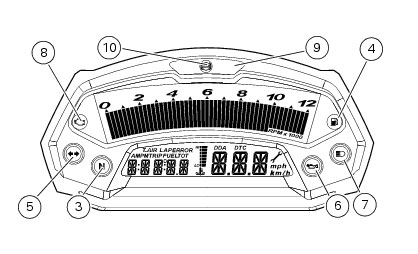
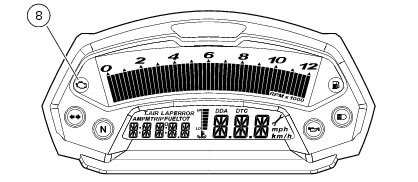
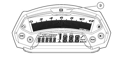
The service indicator will remain on the display until reset.
Instrument panel diagnosis
Important
The instrument runs the system diagnosis correctly 60 seconds after the last Key-Off.
 
This function allows you to display and identify malfunctions of the motorcycle and, where possible, renew components identified as faulty.
 
To display this function, enter the menu and select the “Error” page.
This menu is only present if at least one error is detected, otherwise this page will NOT appear.
If there are several errors, they are displayed in rolling mode every 3 seconds.
In any case, a more detailed diagnosis can be obtained using the Ducati Diagnostic System.
Warning
Every time an error is displayed, always contact an authorised Ducati Service Centre.
 
Battery voltage indicator (BATT)
To display this function, go into the menu and select the “BATT” page.
The battery voltage reading is displayed as follows:
-
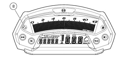
if the reading is between 12.1 and 14.9 Volts, it is steadily illuminated on the display;
-
if the reading is between 10.0 and 12.0 Volts or between 15.0 and 16.0 Volts, it flashes on the display;
-
if the reading is less than or equal to 9.9 Volts, the message “LO” flashes on the display and the “EOBD engine diagnostics” warning light (8) comes on;
-
if the reading is greater than or equal to 16.1 Volts, the message “HI” flashes on the display and the “EOBD engine diagnostics” warning light (8) comes on.
Engine idle speed adjustment (rpm)
To display the function, access the menu and select the “RPM” page.
In addition to the upper rev counter scale, the display also shows engine rpm numerically so that you can adjust the idle speed more precisely.
Backlighting adjustment
To adjust the backlighting, enter the menu and select the “LIGHT SET” page.
 
Press the switch (1) in position B “t” for 3 seconds in this page to access the setup mode and the following pages will be dis­played in sequence:
 
page 1 - “LIGHT MAX” setting:
This page sets backlighting to maximum brightness; press switch (1) in position B “t” to go to page 2.
 
page 2 - “LIGHT MID” setting:
This page reduces the backlighting by approximately 30% relative to maximum brightness; press switch (1) in position B “t” to go to page 3.
 
page 3 - “LIGHT MIN” setting:
This page reduces the backlighting by approximately 70% relative to maximum brightness; press switch (1) in position B “t” to go to page 1.
 
If you press the button (1) in position B “t” for 3 seconds in one these three pages, the instrument panel goes back to the “LIGHT SET“ page and stores the selected backlighting setup.
 
In the event of an interruption of the power supply from the battery, when power is restored at the next Key-On, the backlighting will be set by default to maximum brightness.
LAP function
To enable this function, enter the menu and set the “LAP“ function to “On“ by holding switch (1) pressed in position B “t“ for 3 seconds.
 
START and STOP the timer by pressing the high beam FLASH switch (2) on the left-hand handlebar switch.
When the LAP function is active, each time you press the flasher switch, the display will show the lap time for 10 seconds, before reverting to normal mode.
You can save a maximum of 30 laps in the memory.
If the memory is full, each time you press the flasher switch, the display will not save any more lap times and will display the flashing message “FULL” for 3 seconds until the memory is reset.
When you switch the LAP function off from the menu, the lap in progress will not be saved.
If the LAP function is active and the display is suddenly switched off (Key-Off), the LAP function is switched off automatically (even if the timer was ON, the lap in progress is not saved).
If the lap timer is not stopped, it will roll over upon reaching 9 minutes, 59 seconds and 99 hundredths; the lap timer starts count­ing from 0 (zero) and will keep running until the function is disabled.
If, however, the LAP function is switched on and the memory has not been cleared, but fewer than 30 laps have been saved (e.g. 18 laps), the display will save any remaining laps until the memory is saturated (in this case, it will save a further 12 laps).
This function only displays lap times once; however, lap times are saved for subsequent display in the Lap Memory function.
LAP Memory display
Displays the data saved using the LAP function: lap number and time.
To display the saved lap times, enter the menu and select the “LAP MEM” page.
Holding switch (1) pressed in position B “t“ in this menu page accesses the “1st lap“ view mode. The display will show the lap number, lap time, MAX speed and the MAX rpm reached for the lap in question.
Press switch (1) in position B “t“ repeatedly to scroll through the 30 laps stored until returning to the 1st lap.
If you press switch (1) in position B “t“ for 3 seconds while the saved times are displayed, the display immediately resets all the saved times; in this case, if the LAP function was active, it is switched off automatically.
The MAX speed saved is the maximum speed indicated on the display in Lap function.
To exit display of the lap times memory press switch (1) in position A “s”.
If no lap times are saved in memory, all 30 lap times will be displayed as “0.00.00”.
If the engine trips the rev limiter during a lap, the “OVER REV.” indicator light will come on during display of the lap time. (9).
DDA data acquisition
This function serves to activate the DDA (Ducati Data Analyzer): in order to acquire data, the DDA must be connected to the mo­torcycle wiring loom.
To enable data acquisition, enter the menu and set the “DDA“ function to “On“ by holding switch (1) pressed in position B “t“ for 3 seconds.
To START and STOP the lap separator press the high beam FLASH button (2) on the left-hand handlebar switch.
If the DDA function is active and the motorcycle is suddenly switched off (Key-Off), the function is switched off automatically.
Note
Online assistance is available to Ducati Data Analyzer (DDA) owners (http://dda.prosa.com). This service will provide anything nec­essary to correctly use the DDA with your PC: both for the device and the software for analysing the recorded data.
Warning
After use, disconnect the DDA from the main wiring harness.
 
Erase DDA
This function enables you to delete the data saved on the DDA: the DDA must be connected to the motorcycle wiring.
To delete the data, enter the menu and select the “Erase DDA” page.
If you press switch (1) in position B “t“ for 3 seconds and the DDA is not acquiring data, the message “WAIT…” is shown on the display for 10 seconds. After 10 seconds, the message “ERASE OK” appears for 3 seconds, to confirm that the DDA data has been deleted.
If switch (1) is pressed in the B “t“ position for 3 seconds while the DDA data logger is acquiring data, the data logger memory is not erased and the display shows message “FAIL“ for 3 seconds.
ABS disabling function
This function disables the ABS control unit.
 
This operation must be carried out with the vehicle stopped (key ON).
 
To disable the ABS control unit, access the menu on the “DISAB ABS” page and hold down switch (1) in position B “t“ for
3 seconds.
At the end of the 3 seconds, the flashing ABS light (10) on the instrument panel indicates the disabling.
 
From this moment, the ABS control unit is disabled; it is automatically re-enabled at the next Key-Off / Key-On.
 
At the next Key-On the instrument panel indicates that it is operative by keeping the ABS light (10) off.
 
If there are problems with the ABS system, the instrument panel indicates its malfunction by keeping the ABS light (10) on steady, the EOBD light (8) on steady and the ABS error in the menu.
Important
This indicator is activated only at a speed above or equal to 10 km/h; at a speed lower than 10 km/h the ABS control unit does not perform the diagnostics.
Clock setting function
To set the clock, enter the menu and select the “SET” page.
Holding switch (1) pressed in position B “t“ for 3 seconds in this menu page gives access to the setup mode.
On entering this mode, the message “AM” will flash; if you press switch (1) in position B “t” the message “PM” flashes; if you press switch (1) in position B “t” the mode will go back to previous setting (if it is 00:00, when toggling from “AM” to “PM”, 12:00 will be displayed). Pressing switch (1) in position A “s“ gives access to the hour setting mode; hours start to flash. Each time you press the button in position B “t“, the digit will increase by one hour. If the switch is held pressed in position B “t” the number increases cyclically in steps of one hour every second (when the switch is held depressed, the hours do not flash).
Pressing switch (1) in position A “s“ gives access to the minute setting mode; minutes start to flash. Each time you press the button in position B “t“, the digit will increase by one minute. If you hold the switch down in position B “t”, the count increases cyclically in steps of 1 minute every second. If the button is held depressed in position B “t“ for over 5 seconds, minutes will increase by 1 minute every 100ms (while the button is held depressed in position B “t“, seconds will not flash). Pressing the button in position A “s“, exits setup mode and the new time is displayed.
Note
If the power supply is disconnected (Battery-Off), the time setting is lost. When power is restored (Battery-On), the display will show 0:00. Set the time according to the normal procedure.
Programming the immobilizer
This instrument panel function enables programming of the Immobilizer System.
Note
Only 2 keys may be programmed.
 
Insert KEY 1 (one of the two black keys) and turn the ignition switch from Off to On;
within 3 seconds turn the ignition switch from On to Off;
within 15 seconds insert KEY 2 (the other black key) and turn the ignition switch from Off to On;
within 3 seconds turn the ignition switch from On to Off;
within 15 seconds, insert KEY X again (either Key 1 or Key 2) and turn the ignition switch from Off to ON.
If the procedure was successful, the instrument panel will display the message “PROG. OK” steadily for 3 seconds before re­turning to the normal display mode.
Programming aborted:
if you allow the 3 second countdown after Key-On or the 15 second countdown after Key-Off to elapse, or you make a mistake in the programming procedure, the instrument panel will abort the programming operation and display the message “PROG OFF” for 3 seconds before returning to normal display mode.
Important
During the programming procedure, the instrument panel, in addition to saving the key codes in its memory, retrieves two “elec­tronic” codes from the insertion of KEY 1 (the first black key to be inserted) and KEY 2 (the second black key to be inserted).
 
If the immobilizer is reprogrammed, the key codes will be erased and replaced with the new codes of the new keys; the two “electronic” codes, however, remain permanently in memory and cannot be deleted or overwritten.
The code on the Code Card corresponds to one of the two electronic codes and is used for the Immobilizer Recovery and Immo­bilizer Reprogramming procedures.
Immobilizer override procedure
Should the immobilizer become locked, you can perform the “Immobilizer Override” procedure from the instrument panel by entering the respective function as described below.
Select the “CODE” page from the menu.
Note
This menu should be active only if there is at least one immobilizer error.
 
With this page selected, the initial code is always displayed as “00000”. If you hold pressed switch (1) in position B “t“ for
3 seconds, you will access the procedure for entering the electronic code given on the Code Card.
 
Entering the code:
on entering this function, the first digit on the left starts flashing.
 
Switch (1):
each time you press the switch in position B “t”, the number increases cyclically in steps of one digit every second;
if you press the switch in position A “s”, you can set the second digit, which will start flashing. Each time you press the switch in position B “t”, the number increases cyclically in steps of one digit every second;
if you press the switch in position A “s”, you can set the third digit, which will start flashing. Each time you press the switch in position B “t”, the number increases cyclically in steps of one digit every second;
if you press the switch in position A “s”, you can set the fourth digit, which will start flashing. Each time you press the switch in position B “t”, the number increases cyclically in steps of one digit every second;
if you press the switch in position A “s”, you can set the fifth digit, which will start flashing. Each time you press the switch in position B “t”, the number increases cyclically in steps of one digit every second;
press in position A “s” to confirm the code.
If the code entered is incorrect, the instrument panel will automatically return to the “CODE” menu and display the code “00000”.
If the code has been entered correctly, the message CODE and the code itself will flash simultaneously for 4 seconds. The EOBD diagnostics warning light (8) will go off. The instrument panel then automatically exits the menu, thus temporarily allowing the motorcycle to be started.
If the error is still present, at the next Key-On the instrument panel error and the inhibited status will persist.
Intelligent headlight switch-off
This function helps reduce battery use by automatically switching off the headlight. The device is triggered in 3 cases:
-
in the first case, if you turn the key from OFF to ON and do not start the engine within 60 seconds, the headlight is turned off and will be turned on again only when the engine is next switched on;
-
in the second case, after the normal use of the motorcycle with the lights on, if the engine is stopped using the RUN-STOP button on the right-hand handlebar switch. In this case, the headlight is switched off 60 seconds after the engine is switched off, and only switched on again the next time the engine is started;
-
Intelligent headlight switch-on
This function allows programmed activation of the headlight even with the motorcycle off (Key-Off).
The instrument panel stays active for 60 seconds soon after Key-Off, and the headlight can be switched on by pressing switch (1) in position A “s“ or B “t“.
During these 60 seconds, each time switch (1) is pressed in position A “s” or B “t”, the instrument panel will activate the headlight for 30 seconds; each press of the switch will add to the headlight activation time, up to a maximum of 6 presses (equiv­alent to a maximum activation time of 180 seconds).
After the first time you press switch (1) in position A “s” or B “t”, the period of 30 seconds starts, thus switching on the head­light. Further switch-on time can be added only if you press the switch again within these 30 seconds. If the 30 seconds have elapsed, no further multiples of 30 seconds can be added, and the instrument panel will switch off the headlight.
To reset this function, you must perform at least one Key-On/ Key-Off.
If the battery power is interrupted at any time while this function is active, when power is restored, the instrument panel will de-activate the function (the instrument panel does not remain active for 60 seconds).
Service Menu
The instrument panel has a service menu, which must be used only by the dealer if necessary.
To enter the service menu, press and hold button (1) in position A “s” while turning the ignition switch from “Off” to “On”.
Note
Within this “MENU” all other functions are excluded and motorcycle starting is disabled.
 
The very first Function to be displayed is the “Immobilizer Reprogramming” procedure (00000 PRO).
Now, push button A “s” to display the “Setting Special” Function (UNIT SET).
After having made the required changes, turn the key from “ON” to “OFF” to save the new settings in memory.
The new parameter settings will be applied at the next Key-On.
Immobilizer Reprogramming (service menu 1)
This function is for reprogramming the immobilizer system in the event of loss or damage to one or both of the keys.
To display this function, go into the service menu and select the page “0000 COD”.
Note
Within this function all other functions are excluded and motorcycle starting is disabled.
 
On entering this page, the initial code is always displayed as “00000”. If you hold pressed switch (1) in position B “t“ for
3 seconds, you will access the procedure for entering the electronic code given on the CODE CARD.
Entering the code:
the first digit on the left flashes;
each time you press the switch in position B “t”, the number increases cyclically in steps of one digit every second;
if you press the switch in position A “s”, you can set the second digit, which will start flashing. Each time you press the switch in position B “t”, the number increases cyclically in steps of one digit every second;
if you press the switch in position A “s”, you can set the third digit, which will start flashing. Each time you press the switch in position B “t”, the number increases cyclically in steps of one digit every second;
if you press the switch in position A “s”, you can set the fourth digit, which will start flashing. Each time you press the switch in position B “t”, the number increases cyclically in steps of one digit every second;
press in position A “s” to confirm the code.
At this point, if the code was entered incorrectly, the display will show the initial code “00000”. There is no limit to the number of times the code may be entered incorrectly.
if you press the switch in position A “s”, you can set the fifth digit, which will start flashing. Each time you press the switch in position B “t”, the number increases cyclically in steps of one digit every second;
If the code has been entered correctly, the message “COD” and the code entered will flash simultaneously until Key-Off.
From this moment on, the immobilizer system is waiting to be programmed with the new key (or keys); at the next Key-On, re­program the keys using the procedure described in “Programming the immobilizer”.
Note
During this stage, the immobilizer system will immobilise the engine until the keys have been reprogrammed.
Loss of the Code Card
Without knowing the electronic code on the CODE CARD, it is impossible to:
reprogram the immobilizer system in the event of loss of one or both of the keys;
temporarily override the immobilizer in the event of a fault.
To restore the entire system to full operation, it is necessary to renew the KEY SET (2 black keys + new CODE CARD) and the instrument panel, and therefore programme the immobilizer again.
Loss of one key
After purchasing a new key, perform the Reprogramming procedure (by entering the code shown on the CODE CARD) with the new key and the remaining key.
Loss of both keys
After purchasing two new keys, perform the Reprogramming procedure (by entering the code shown on the CODE CARD) with the new keys.
Renewal of the instrument panel
After purchasing the new instrument panel, perform the normal “Programming” procedure for the immobilizer system.
Renewing the instrument panel after renewing one or both of the keys
In this case, if you want the immobilizer to be fully functional, before programming the immobilizer, first renew the KEY SET as well (2 black keys + new CODE CARD).
If the new instrument panel is programmed with the keys previously renewed, it will be possible to start the motorcycle but the electronic code shown on the CODE CARD will no longer enable you to:
reprogram the immobilizer system in the event of loss of one or both of the keys;
temporarily override the immobilizer in the event of a fault.
Special settings - vehicle model and units of measurement (service menu 2)
This function allows you to select the units of measurement displayed on the instrument panel.
The ECU automatically communicates to the instrument panel the motorcycle model and the units of measurement to be used on the display: to change these parameters, go into the “Service Menu ” and select the “UNIT SET” function.
Note
Within this function all other functions are excluded and motorcycle starting is disabled.
 
Now press button (1) in position B “t” for 3 seconds.
Every time you press button (1) in position B “t”, the Dashboard toggles through the following flashing values:
The instrument configures the unit of measurement param­eters in accordance with information relayed from the ECU
Press button (1) in position B “t” for 3 seconds to store the displayed settings, the message “MEM” confirms storage. The new parameter setting will applied at the next Key-On.
P