8 -
The immobilizer allows the vehicle to be started only if the rider uses the special ignition key which sends the identification code to a decoder housed in the instrument panel. The transmission-receiving system is composed of a TRANSPONDER housed in the ignition key heads and an antenna in the vicinity of the ignition switch.
Keys with transponder
The two keys contain the secret code used for programming the immobilizer and allowing the engine to be started.
The transponder is fitted inside the key grip and consists of a power supply circuit, a ROM (Read-Only Memory) and a transmis­sion circuit. The transponder is supplied with power by the magnetic field generated by the antenna which is enabled as soon as the instrument panel is switched on. Since the transponder is very compact and needs no external battery power supply, it is moulded permanently into the key grip.
Warning
The circuits in the key grips are not shockproof and may therefore be damaged by violent impact.
Immobilizer antenna
The antenna consists of a plastic-coated copper coil connected to a cable that is terminated with a connector.
The antenna (A) is fitted onto the ignition lock cover (B), which is specifically modified for the purpose to create a seat in which the antenna is inserted and restrained.
Immobilizer operating principle
At key-on (switching on the instrument panel by turning the key) the decoder (incorporated in the instrument panel) activates the antenna, which emits an electromagnetic field that serves to power the transponder in the key grip. The transponder responds by transmitting the code that is stored on its internal ROM memory, and which is picked up by the antenna and relayed to the decoder. Here the transponder code is compared to a second code. If the outcome of the comparison is positive, engine starting is enabled.
Warning light signals and immobilizer indications
Whenever the ignition key is turned from ON to OFF, the immobilizer system activates the engine start protection system.
When the engine is started and the key is turned from OFF to ON, the system generates the following signals:
-
-
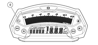
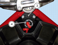
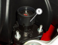
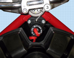
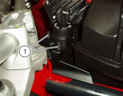
if the code is not recognised, the EOBD diagnostics warning light (8) comes on. Press button (1) in position A “s” to view the page showing “Error” message and a code indicating the type of IMMO fault. In this case, refer to the procedures described in the previous chapter among instrument panel functions.
Removal of the immobilizer
Set the ignition switch to OFF.
Disconnect the antenna wiring connector (A) from the main wiring loom.
Unscrew the two nuts (1) and remove the cover (2).
Undo the screw (3) fastening ignition switch cover (4) and remove the cover (4).
Slide out the immobilizer antenna (5) from ignition switch.
Refitting the immobilizer
Refitting is the reverse of removal; in particular, tighten the screw (3) and nuts (1) to the specified torque (Sect. C 3, Frame torque settings).
 
P