|
3
|
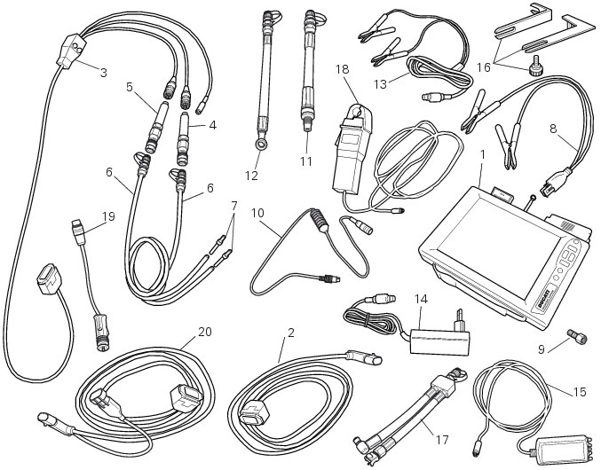
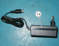
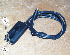
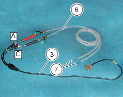
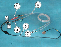
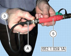
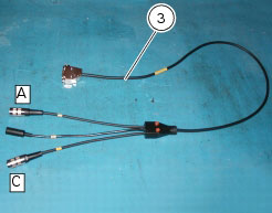
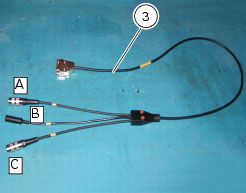
97900.0222 Power and diagnostic cable 1060838
(Measurement Module) |
|
11
|
|
-
|
|
-
|
|
-
|
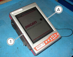
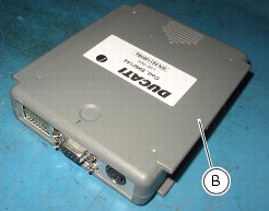
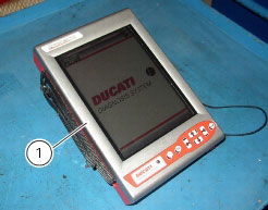
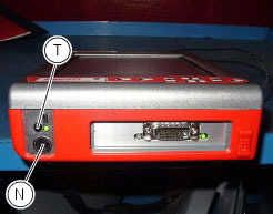
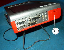
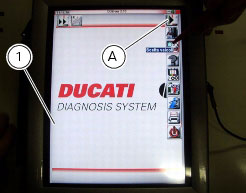
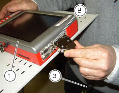
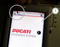
from the tester's internal battery: the battery (Q) is housed in the top part of the tester. To operate the tester (1) using the internal battery and to recharge the battery, refer to the “User Manual” supplied with the DDS diagnosis instrument.
|
|
-
|
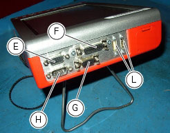
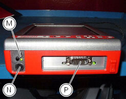
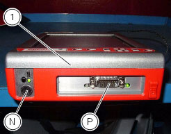
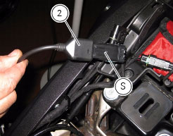
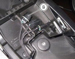
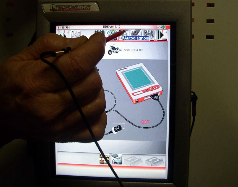
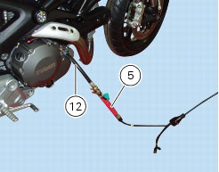
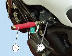
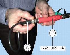
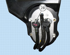
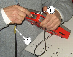
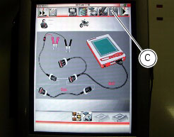
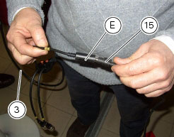
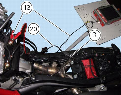
connect the power and diagnostic cable (2) to the diagnostic connection socket (P) on the tester; then connect the motorcycle DDA socket (S) to the connection socket of the power and diagnostic cable.
|

|
-
|
|
-
|
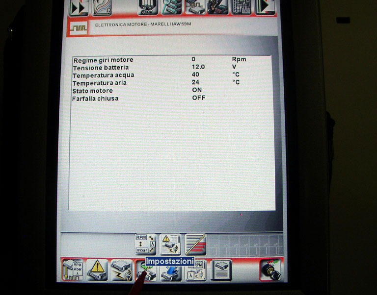
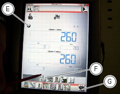
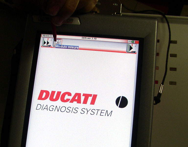
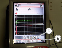
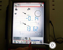
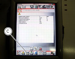
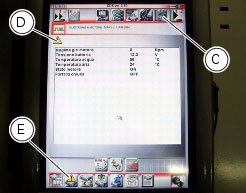
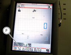
Reading of engine parameters (rpm, coolant and air temperature, atmospheric pressure, throttle opening, battery voltage, injection times and ignition advance, etc.).
|
|
-
|
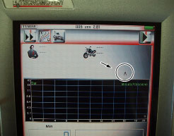
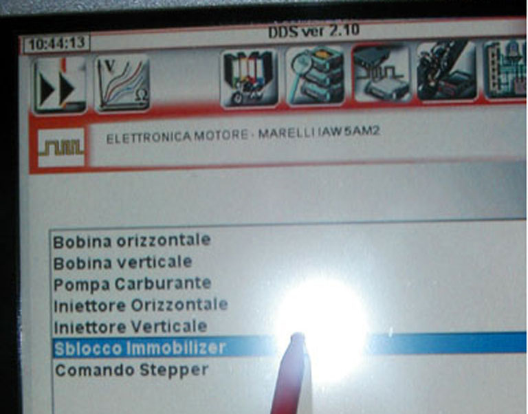
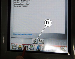
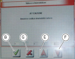
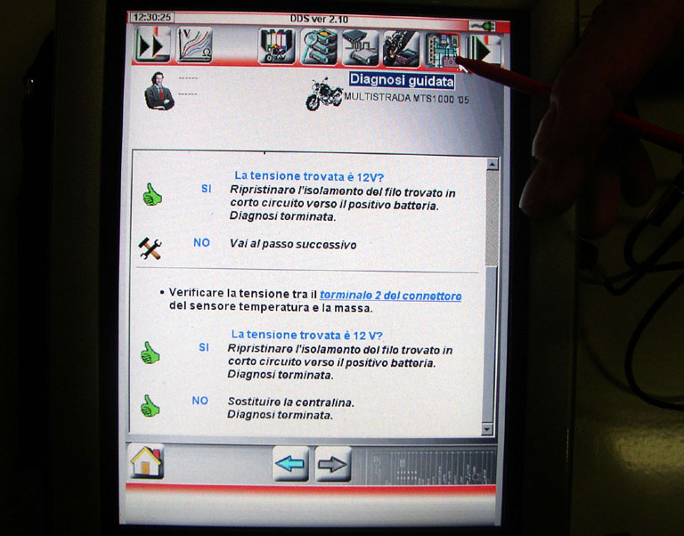
Active diagnostics. Activation of ignition-injection system transducers to test functionality and control signals (fuel pump, ignition coils, rev counter, injectors, etc.). With this function it is also possible to enter the code to override the immobilizer.
|
|
-
|
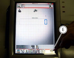
Road test. Allows the technician to store engine parameters recorded within a previously specified engine speed range interval. The resulting parameters can then be analysed and displayed once they have been acquired.
|
|
-
|
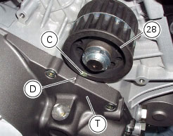
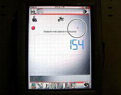
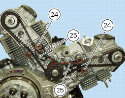
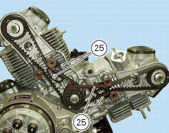
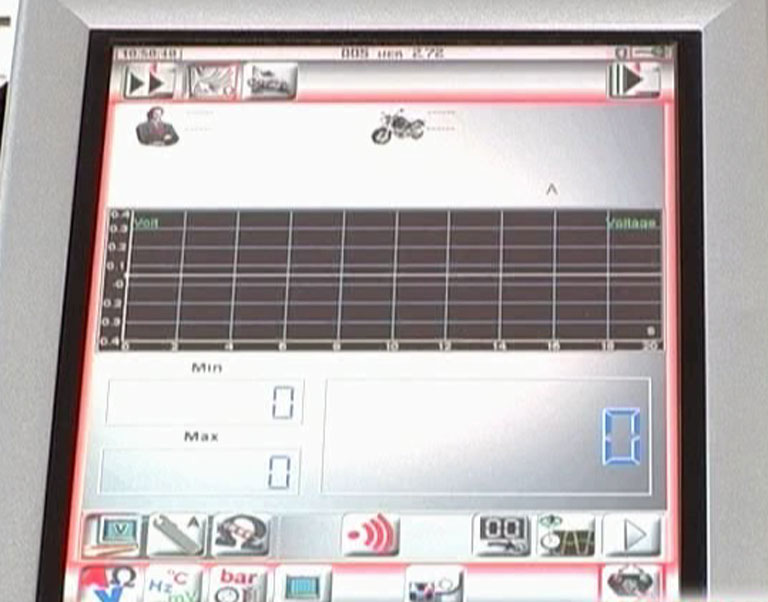
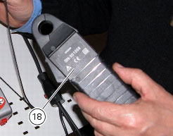
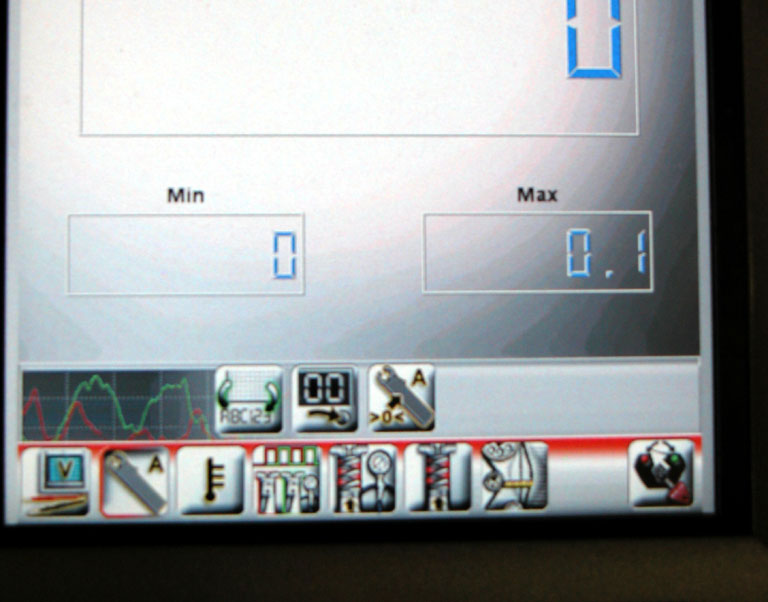
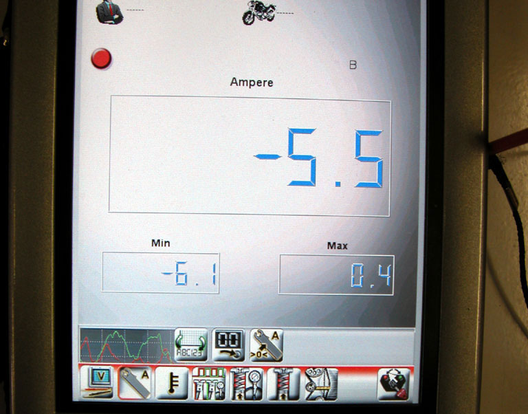
With specific sensors connected, the DDS diagnosis instrument can read electrical voltages, current, temperature, timing belt tension, and pressure values (lubrication and fuel supply circuits for example).
|


|
-
|
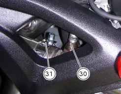
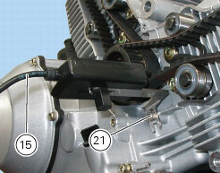
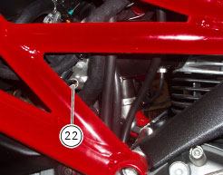
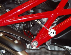
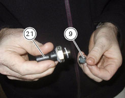
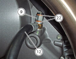
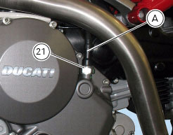
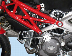
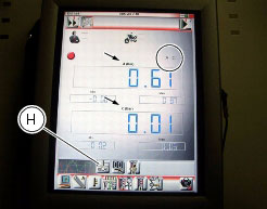
If idle speed is lower or higher the specified values, open or close by 1/4 of a turn the by-pass screws (21) and (22) on both cylinders; once idle speed is fine, check that the CO rate is above 0.4% in both cylinders.
|

|
-
|
If you are unable to attain the desired idle speed setting, try reducing the vacuum differential downstream of the butterfly valve as described in the following paragraph “Throttle body balancing”.
|


|
-
|
|
-
|
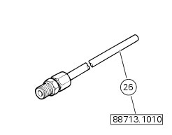
minimum value: 10 bar;
|


|
|
|
|
|
|
|
|
|
|
|
|
|
|
|
|
|
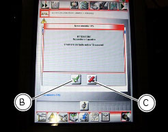
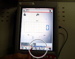
Menu 1
|
|
|
|
|
|
|
|
|
|
|
|
|
|
|
|
|
|
|
|
|
|
|
|
|
|
|
|
|
|
|
|
|
|
|
|
|
|
|
|
|
|
|
|
|