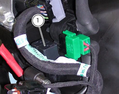
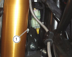
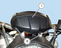
4 -
Renewal of the headlight
Undo the screws (8) and remove the instrument panel shroud (1).
Disconnect the instrument panel connector (A) from the main wiring (refer to the tables under “Routing of wiring on frame“, Sect. P 1).
Disconnect the headlight connector (B) and the front turn indicator connectors from the main wiring harness (refer to the tables under “Routing of wiring on frame”, Sect. P 1). Unscrew the nuts (2) securing the front light assembly to the bottom yoke.
Remove plate (C) that is released when loosening nut (2) on the left-hand side.
Remove the complete headlight sliding out pins (D) from the mounting bracket.
Release the headlight from the front light assembly by unscrewing the screws (3).
Remove the front turn indicators (4) by removing the circlip (5) and unscrewing the screw (6).
Note
The US version fits a spacer (T) between turn indicator and headlight mount.
Refitting is the reverse of removal: if removed, refit the rubber blocks (7) to headlight finger-tight, apply a drop of clear universal silicone onto rubber block (7) where indicated.
Duly install the safety washers (8) onto rubber block.
Note
Ensure the two safety washers are perfectly glued onto rubber block and can not come off.
If removed, reposition the turn indicators to headlight mount, with the drain slot (F) facing down; position the stop plate (5) as shown.
Apply the recommended threadlocker to the screws (6). Start the screws (6) in their thread ensuring that the slot on stop plate (5) perfectly matches the tabs on turn indicators. Tighten the screws (6) to the specified tightening torque (Sect. C 3, Frame torque settings).
Note
For the US version you shall install spacer (T) between turn signal and headlight mount. Position spacer with slot facing down. Route the turn signal wiring through the slot on spacer bottom, ensuring not to leave it too taut or the fast-on connectors inside the turn indicators might detach.
Position the headlight to the headlight mount and set it as shown, ensuring that the turn indicator wiring is not squashed under the headlight.
Fit the spacers (7) and the screws (3). Tighten the screws (3) to the specified torque (Sect. C 3, Frame torque settings).
Position the headlight cover (8), setting it as shown onto headlight mount (9).
Insert a spacer (7) to a screw (10), positioning it as indicated.
Start screw (10) in its thread on the central clip (11) of headlight cover (8).
Start the other two screws (10) in their thread on the side clips (11) of headlight cover (8).
Tighten the screws (10) to the specified torque (Sect. C 3, Frame torque settings).
Reconnect headlight (B) and turn indicator (E) connectors.
Reconnect the instrument panel wiring (A).
Position connector (B) onto plate (C) and the latter on the bottom yoke, fastening it with nut (2). Tighten the nuts (2) to the spec­ified torque (Sect. C 3, Frame torque settings).
Refit the instrument panel cover (1) and tighten the screws (8).
Changing bulbs
Changing the headlight bulbs
Before replacing a burnt out light bulb, ensure that the replacement bulb has the same voltage and power rating as specified for the lighting device in question (Sect. C 1.1, Lights/instrument panel).
Warning
The halogen light bulbs in the headlight become hot when switched on and remain hot for some time after they are switched off. Allow bulbs to cool before replacing them.
 
The position of the light bulbs in the headlight is as indicated below: low beam (LO), high beam (HI) and parking light (A).
Remove the headlight, as described in the paragraph “Renewal of the headlight“ of this section.
To access the headlight bulb unscrew the four screws (1) and remove the cover (2).
High beam (HI)
Disconnect the wiring connector (3) from the headlight bulb (4).
Release the retaining clip (5).
The bulb (4) has a bayonet base: press and twist counter clockwise to remove.
Fit the new bulb (4), insert the tabs on the bulb base into the corresponding slots to ensure the bulb is correctly positioned, push the bulb in and turn clockwise until it clicks into place.
Refit connector (3) to lamp (4), cover (2) to headlight, then tighten the screws (1) to the specified torque (Sect. C 3, Frame torque settings).
Low beam (LO)
To change the Lo beam headlight bulb (6) see the procedure described above for the Hi beam headlight bulb.
Replace the bulb with a new one of the same type and rating (Sect. C 1.1, Lights/instrument panel).
Note
Do not touch the transparent part of the bulb with your fingers, this will darken it and cause a loss of brightness.
Side lights (A)
To replace the side light bulb, withdraw the bulb holder (7) from the rear of the headlight. Extract the bulb and renew it.
Changing the number plate light bulb
To access the bulb in the number plate light (8), open the number plate lens, pull the bulb out of the holder and renew it.
High beam headlights relay
Located alongside the battery and fixed to the battery support. To reach this component it is necessary to remove the seat, so insert the key in the lock and simultaneously apply downward pressure in the area of the catch to release the pin.
Pull the seat backwards to release it from the front catches and remove it from the frame.
Remove the tank covers (Sect. E 2, Removal of the fuel tank fairings).
Remove the fuel tank (Sect. L 2, Removal of the fuel tank).
Remove the elastic retaining strap (2) and slide out the battery (1).
The high beam relay (1) has been added to the electrical circuit to enable the lights power down strategy. This strategy is as fol­lows:
1
if the lights are on during normal riding, they switch off 60 seconds after pressing the engine Stop button (2) and key ON; they switch back on the moment the motorcycle is started again;
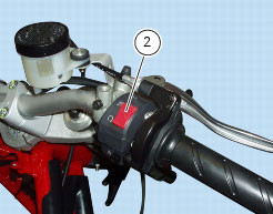
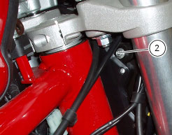
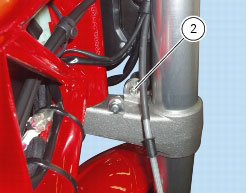
2
if the lights are switched on, they will switch off automatically after 60 seconds after key ON if the engine remains stopped.
If this strategy is not performed, check the correct operation of the various parts involved.
Checking operation of the high beam lights relay
Disconnect the relay (1) from the electrical system and apply 12 V (battery voltage) between contacts (86) and (85) (small con­tacts): you should hear a click that confirms that the internal electromagnet has switched.
Connect a multimeter to contacts (30) and (87) (big contacts) to check for the full scale reading (analogue tester) or buzzer (digital tester). If this does not occur, the part must be renewed.
Refitting is the reverse of removal.
Headlight aim
The motorcycle must be perfectly upright with the tires inflated to the correct pressure and with a rider seated, perfectly perpen­dicular to the longitudinal axis.
Position the motorcycle 10 metres from a wall or a screen.
On the wall or surface, draw a horizontal line at the same height from the ground as the centre of the headlight and a vertical line aligned with the longitudinal axis of the motorcycle.
Note
If possible, perform this check in conditions of low ambient light.
 
Switch on the low beam. The height of the upper limit between the dark area and the lit area must not be more than nine tenths of the height of the centre of the headlight from the ground.
Note
This is the procedure specified by Italian regulations for checking the maximum height of the light beam.
The vertical alignment of the headlamp can be adjusted manually by turning screw (1).
Turn the screw (2) to set beam height.