6 -
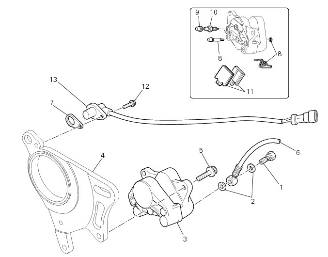
Hydraulic rear brake
1
Banjo bolt
2
Sealing washer
3
Rear brake calliper
4
Calliper mounting bracket
5
Screw
6
Control unit - rear calliper pipe
7
Spacer
8
Pin and clip
9
Dust cap
10
Bleed valve
11
Pair of brake pads
12
Screw
13
Speed sensor
Spare parts catalogue
1100 ABS
Rear brake
1100 ABS
REAR WHEEL AXLE
1100 S ABS
Rear brake
1100 S ABS
REAR WHEEL AXLE
Important
Bold reference numbers in this section identify parts not shown in the figures alongside the text, but
which can be found in the exploded view diagram.
Removal of the rear brake calliper
Important
The brake master cylinder manufacturer advises against servicing the brake master cylinder due to the safety critical nature of
this component. Incorrect overhaul of this component could endanger rider safety.
Operations should be limited to renewal of the pads, fasteners and the bleed valve assembly.
Operation
Section reference
Draining the brake system
D
4,
Draining the brake circuit
Slacken the chain
D
4,
Adjusting the chain tension
Remove the rear wheel
G
4,
Removal of the rear wheel
Remove the lower fairing protections
G
5,
Removal of the swingarm
Note
For the ABS rear braking system, also refer to Sect. G 9.1,
ABS system operating information
, Sect. G 9.2,
System components
, Sect. G 9.3,
ABS components maintenance
.
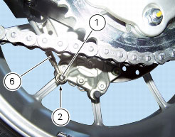
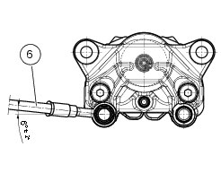
Unscrew and remove the banjo bolt (1) securing the hose (6) to the rear brake calliper and recover the sealing washers (2).
Note
Keep a cloth at hand to wipe up any brake fluid that leaks out of the hose.
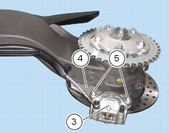
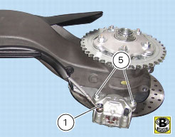
Unscrew the screws (5) securing the rear brake calliper (3) to the calliper mounting bracket (4) and remove the calliper.
Note
To replace the brake pads, please refer to Sect.
D 4,
Checking brake pad wear and changing brake pads
.
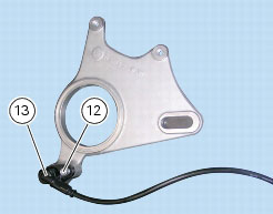
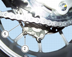
To remove the speed sensor (13), undo the screw (12) securing it to the calliper mounting bracket, taking care not to damage the
spacer (
7
).
Only the following parts should be renewed:
brake calliper: pads, fasteners and bleed valve assembly;
master cylinder: control pedal, bleed valve assembly, reservoir and its components.
Refer to the exploded view at the beginning of this section for indications on renewal of the above components.
Refitting the rear brake calliper
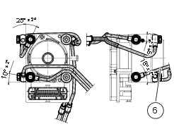
When replacing the brake lines or removing one of the rear braking system components, pay special attention to the position of
the couplings on the master cylinder, callipers and control unit.
Warning
If incorrectly positioned, the hose can affect brake operation and foul moving parts.
If the speed sensor (13) was removed, fit it on the calliper holder bracket with the spacer (
7
) and tighten the screw (12) to the specified torque (Sect. C 3,
Frame torque settings
).
Fit the copper sealing washers (2) to either side of the hose end fitting when connecting the brake hose (6) to the brake calliper.
Orientate the end fittings of the hose (6) on the calliper as shown in the photo.
Tighten the special screws (1) to the specified torque (Sect.
C 3,
Frame torque settings
).
Fit the rear brake calliper (3) over the brake disc, aligning it with the holes in the calliper mounting bracket. Grease the threads
and undersides of the heads of the screws (5). Tighten the screws (5) to the specified torque (Sect. C 3,
Frame torque settings
).
Note
The gap between the sensor (13) and the brake disc fixing screw (12) must be within
0.6
to
2.2
mm.
Operation
Section reference
Refit the lower fairing protections
G
5,
Refitting the swingarm
Refit the rear wheel
G
4,
Refitting the rear wheel
Tension the chain
D
4,
Adjusting the chain tension
Fill the brake circuit
D
4,
Filling the brake system with fluid