

|
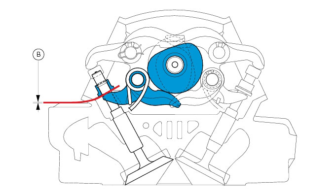
0.10 to 0.15 mm
|
|
|
0.05 to 0.15 mm
|
|
|
0.10 to 0.15 mm
|
|
|
0.05 to 0.15 mm
|
|
|
0 to 0.05 mm
|
|
|
0 to 0.20 mm
|
|
|
0 to 0.05 mm
|
|
|
0 to 0.20 mm
|
|


|
-
|
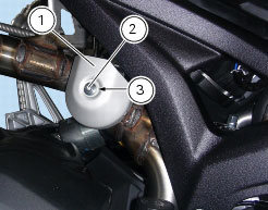
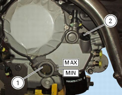
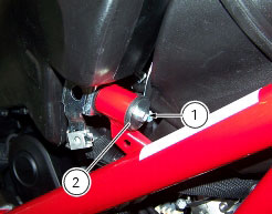
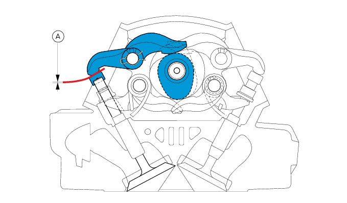
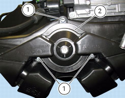
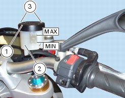
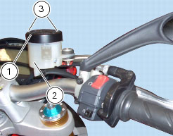
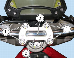
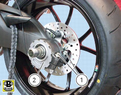
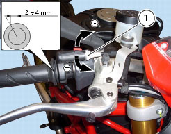
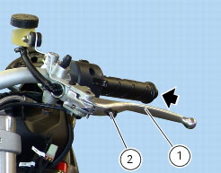
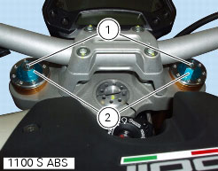
loosen adjuster (1) by 13 clicks.
|
|
-
|
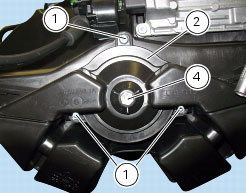
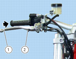
loosen adjuster (1) by 15 clicks.
|