5 -
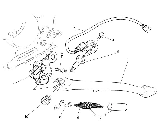
Stands
1
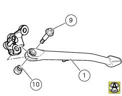
Side stand
2
Screw
3
Support plate
4
Screw
5
Switch
6
Inner spring
7
Spring assembly
8
Plate
9
Pivot screw
10
Nut
Spare parts catalogue
1100 ABS
Stands
1100 S ABS
Stands
Important
Bold reference numbers in this section identify parts not shown in the figures alongside the text, but
which can be found in the exploded view diagram.
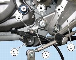
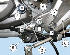
Removing of the sidestand
Unscrew and remove the screw (A) securing the LH footrest bracket (C) to the engine.
Loosen the screw (B) and release the LH footrest bracket (C) from the engine block.
Disconnect the wiring connector (5) of the side stand switch (1) from the main wiring harness.
Unscrew the screw (2) securing the sidestand bracket (3) to the engine and remove the complete sidestand assembly.
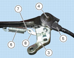
Disassembly of the sidestand
Unscrew the retaining screw (4) and remove the side stand switch (5).
Release the side stand springs (6) and (7) from the connecting plate (8) of the side stand bracket (3) and remove them.
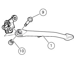
Unscrew the pivot screw (9) securing the side stand to the bracket and remove the side stand (1) and the nut (10).
Inspecting the sidestand
Fit the side stand leg to the bracket and check that there is no excessive clearance. Ensure that the ends of the side stand are
not bent with respect to the shank. A stand which shows signs of cracking must be renewed immediately.
To check the switch (5) refer to Sect.
P 6,
Checking protection and safety device components
.
Reassembling of the sidestand
Grease the side stand leg (1) and fit it to the bracket (3). Secure it with the pivot screw (9) and the nut (10). Tighten the pin (9) to
the specified torque (Sect. C 3,
Frame torque settings
).
Position the side stand return springs (6) and (7) and attach them to pivot plate (8) and stand leg (1).
Place the switch (5) on the bracket, on its pin (9).
Fit the frame fixing screw (4) and tighten it to the specified torque (Sect.
C 3,
Frame torque settings
).
Refitting the sidestand
Locate the side stand bracket (3) between the engine and the LH footrest bracket (C) and fit the screw (2).
Connect the connector (5) of the sidestand switch to the main wiring harness.
To place the stand switch wiring refer to the tables (Sect.
P 1,
Routing of wiring on frame
).
Fit the screw (A) in the footrest bracket (C). Tighten the screws (2), (A) and (B) to the specified torque (Sect.
C 3,
Frame torque settings
), following the indicated sequence.
H