6 -
Checking protection and safety device components
Checking the key switch
Disconnect the ignition key (A) from the electric system by opening its connection (see “Routing of wiring on frame“, Sect. P 1) and use a multimeter to check continuity of its internal connections as follows:
-
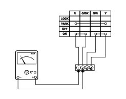
turn the key to OFF and connect a multimeter to contacts (1) and (4) to check electrical continuity (Sect. P 9, Using a multimeter to check the electrical systems, concerning operation of the multimeter). The resistance reading should be near zero and, if present, the audible continuity signal should be emitted;
turn the key to ON and connect the multimeter to contacts (1) and (2) and then to (3) and (4) to check for electrical continuity. The resistance reading should be near zero and, if present, the audible continuity signal should be emitted;
-
turn the key to PARK and connect the multimeter to contacts (1) and (4) to check electrical continuity. The resistance reading should be near zero and, if present, the audible continuity signal should be emitted;
-
turn the key to LOCK and connect the multimeter to contacts (1) and (4) to check for electrical continuity. The resistance reading should be near zero and, if present, the continuity sound signal should be emitted.
Note
The same test may be done using the “DDS” tester (Sect. D 5, DDS diagnosis instrument).
Checking the side stand switch
Remove the switch (1) from the side stand undoing screw (2) and disconnect the main wiring connector from the switch (see paragraph “Routing of wiring on frame“, Sect. P 1).
Use an analogue or digital multimeter (Sect. P 9, Using a multimeter to check the electrical systems) to check switch operation (see table).
Note
The same test may be done using the “DDS” tester (Sect. D 5, DDS diagnosis instrument).
l - s
s - n
Green/
Green
White
Green/
Yellow
Black
0 = Open contact
X = Closed contact
 
Refit switch (1) to side stand and tighten the screw (2) to the specified torque (Sect. C 3, Frame torque settings).
Checking the fuses
The main fuse box (1) is located on the right-hand side of the frame.
The fuses are accessed by removing the cover, which shows the ampere ratings and mounting locations.
For ampere ratings, refer to the chapter “Routing of wiring on frame”, Sect. P 1.
Important
Before replacing a damaged fuse with a new one of the same rating, identify the cause of the problem.
 
A blown fuse can be identified by the breakage of inner filament (A).
Important
Switch the ignition key to OFF before replacing a fuse to avoid possible short circuits.
Warning
Never use a fuse with a rating other than the specified value. Failure to observe this rule may damage the electric system or even cause fire.
 
As well as the fuses in the fuse box, the vehicle has a 30 A fuse (2), located next to the ECU, that protects the electronic regulator (Sect. P 2, Rectifier-regulator).