|
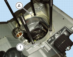
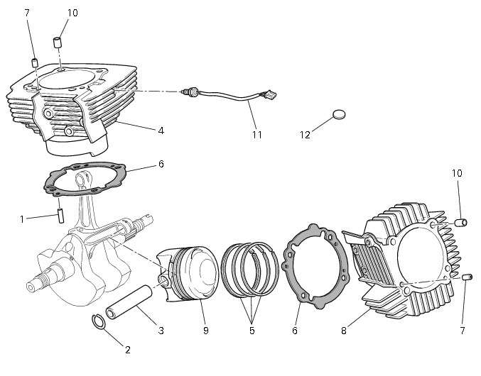
1
|
|
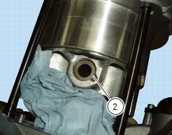
2
|
|
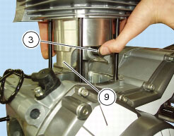
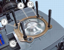
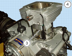
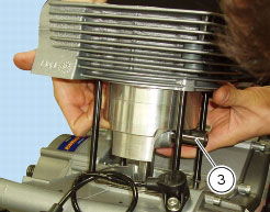
7
|
|
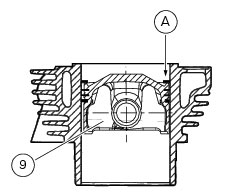
9
|


|
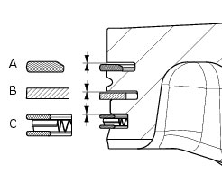
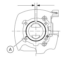
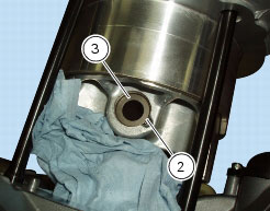
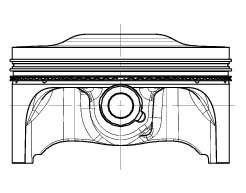
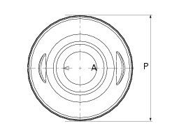
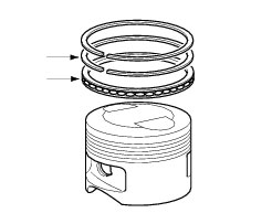
A
|
1st groove
|
|
B
|
2nd groove
|
|
C
|
3rd groove
|