|
2
|
|
4
|
|
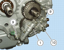
9
|
|
10
|
|
13
|
|
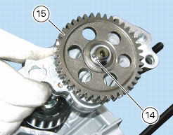
14
|
|
N 6.1, Removal of the clutch
|
|


|
Refit the clutch drum, the clutch centre and the clutch plate pack
|
N 6.1, Reassembling the clutch
|