5 -
Checking the indicating devices
In the event of a fault, the internal connections of the device must be checked in all operating conditions.
To do this, it is necessary to disconnect the switch connector from the main wiring (Sect. P 1, Routing of wiring on frame).
Then analyse the switch using an analogue or digital MULTIMETER (Sect. P 9, Diagnostic instruments).
Note
The same test may be done using the “DDS” tester (Sect. D 5, DDS diagnosis instrument).
Checking the left-hand handlebar switch
To remove the left-hand handlebar switch, undo the fixing screws (1) and disconnect it from the electric system.
The colours mentioned in the following descriptions refer to the colours of the wires from the switch and not to the colours of the wires of the main electric system.
 
HORN button
Connect the terminals of a multimeter to the Blue/White and Brown cables to check for electric continuity, which must be avail­able when HORN is pressed (see Sect. P 9, “Diagnostic instruments“, related to multimeter operation). When HORN button is pressed, resistance value taken by the multimeter should be close to zero and, if available, a continuity beep should be heard. When the horn button is not pressed, the resistance value should be infinity (there is no continuity as the electrical contacts inside the pushbutton are open) and no continuity beep should be heard. If these conditions are not met, the device must be replaced.
 
Turn signal switch (Turn)
Connect the multimeter to the Grey and Brown wires arriving from the turn signal switch and check for electrical continuity when operating the right turn signal (see Sect. P 9, “Diagnostic instruments“, related to operation of the multimeter). Repeat the above procedure for the right turn signal, but connect the multimeter to the (Orange and Grey) wires.
 
Low and high beam headlights (DIMMER).
The test method is the same; connect the meter as follows: (Red/Blue and Light Blue/Yellow).
 
Control switch (MODE)
Connect the multimeter to the Brown and Blue/Yellow wires arriving from the function selector switch and check that when operating the pushbutton in the (s) position there is electric continuity (Sect. P 9, “Diagnostic instruments“, related to operation of the multimeter). Repeat the same procedure, operating the push button in the (t) position, connecting the multim­eter to the Blue/Yellow and Orange cables.
Flasher (PASSING)
Check for continuity between the Red/Blue and Brown cables.
Refit the left-hand switch tightening the screws (1) to the specified tightening torque (Sect. C 3, Frame torque settings).
Checking the right-hand handlebar switch
To remove the right-hand handlebar switch, undo the retaining screws (1) and disconnect the wiring connector from the electric system.
The colours mentioned in the following descriptions refer to the colours of the wires from the switch and not to the colours of the wires of the main electric system.
Engine Stop button
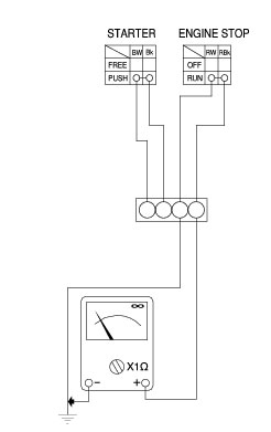
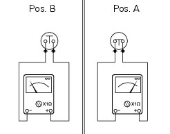
Using a multimeter, check for continuity between the Red/White and Red/Black wires (see Sect. P 9, Diagnostic instru­ments, for information on the operation of the multimeter). When the switch is in the RUN position, there should be electrical continuity between the two wires. When the switch is in the OFF position there should be no electrical continuity between the two wires.
If these conditions are not met, the Engine Stop switch is not working correctly and must be renewed.
 
STARTER button
Proceed as described for the engine stop button and check for continuity between the Blue/White and Black wires when the starter button is pressed (see Sect. P 9, Diagnostic instruments concerning operation of the multimeter). If there is no continuity, the STARTER switch is defective and must be renewed.
 
Refit the right-hand switch tightening the screws (1) to the specified tightening torque (Sect. C 3, Frame torque settings).
Checking the front and rear brake light switches, neutral light switch, oil pressure switch and clutch switch
Brake light switches
To check operation of the front (1) and rear (2) brake light switches use a multimeter to check that when the front or rear brake is pressed, there is electric continuity (Pos. A) between the terminals of the corresponding switch (Sect. P 9, Diagnostic instru­ments, related to operation of the multimeter). When the brake is released, there must be no electrical continuity across the ter­minals of the corresponding switch (Pos. B). If these tests fail to produce positive results, the part in question must be renewed.
Neutral indicator light
To check the neutral light switch (3) proceed as follows.
The neutral light does not illuminate on the instrument panel.
Remove the electric terminal connected to the neutral switch. Switch on the ignition switch (ignition key to ON position) and ensure that the light illuminates when the terminal is earthed. If the light switches on, the neutral light switch should be changed. If the light stays off, switch off the ignition (ignition key set to OFF) to switch off the instrument panel and check for electrical continuity between the neutral switch and engine ECU with a multimeter.
 
The neutral light on the instrument panel is permanently illuminated.
Switch on the ignition (ignition key set to ON) and remove the electrical terminal from the neutral switch. If the light turns off, the neutral switch should be changed. If the light stays off, switch off the ignition (ignition key set to OFF) and use a multimeter to check whether the section of circuit between neutral switch and engine ECU is earthed.
 
Oil pressure sensor
To test the operation of the engine oil pressure sensor (4), proceed as follows.
Use the “DDS“ to check that oil pressure into the engine oil circuit complies with the specified values (Sect. D 5, Check the engine oil pressure).
If the engine oil pressure value is outside the specified range, check the oil circuit components and service as necessary.
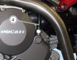
If engine oil pressure value is within the specified range and the oil pressure warning light on the instrument panel stays off, switch on the instrument panel (ignition key set to ON) without starting the engine, and disconnect the electrical terminal from the pressure sensor and connect it to earth. If the warning light now illuminates, this means the sensor is defective and must be replaced. If the warning light does not illuminate, use a multimeter and check for electrical continuity in the section of the circuit between sensor and warning light on the instrument panel (this check must be performed with the ignition key set to OFF, i.e. with instrument panel off).
If the engine oil pressure complies with the stated values and the engine oil pressure warning light on the instrument panel is continuously illuminated, switch on the instrument panel (ignition key set to ON) and start the engine, then disconnect the elec­trical terminal normally inserted on the pressure sensor. If the warning light now switches off, this means the sensor is defective. If the warning light does not switch off, use a multimeter to check that the section of the circuit between sensor and warning light on the instrument panel is not connected to earth (this check must be performed with the ignition key set to OFF, i.e. in­strument panel off).
Clutch switch
For the clutch switch (5) proceed in the same manner as for the brake light switches (see beginning of this paragraph).
Changing light bulbs
Changing the turn signal light bulbs
Undo the screw (1) and detach the lens (2) from the turn signal support (3).
The bulb has a bayonet-type end fitting: to remove it, push it in and turn it counter-clockwise.
To remove the support (3), for the front turn indicators refer to Sect. P 4, Renewal of the headlight, while for the rear turn indica­tors refer to Sect. H 7, Removal of the tail light-protection-number plate holder assembly.
Push in the new bulb and turn it clockwise until it clicks into place.
Refit the lens by inserting the tab (A) in the corresponding slot in the turn signal support.
Tighten the screw (1).