|
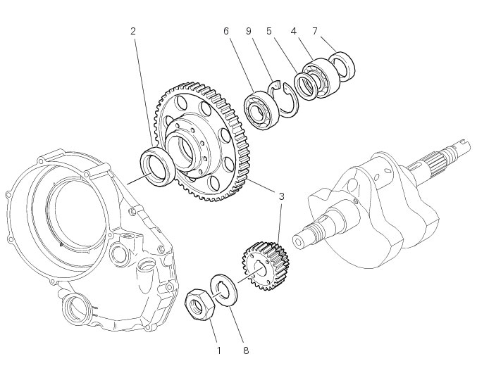
1
|
|
4
|
|
5
|
|
6
|
|
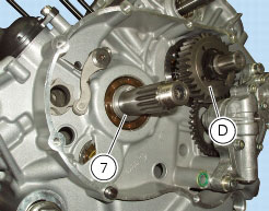
7
|
|
9
|
|
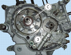
N 6.1, Removal of the clutch
|
|


|
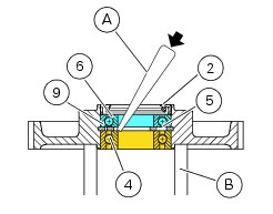
N 6.1, Reassembling the clutch
|
|