2 -
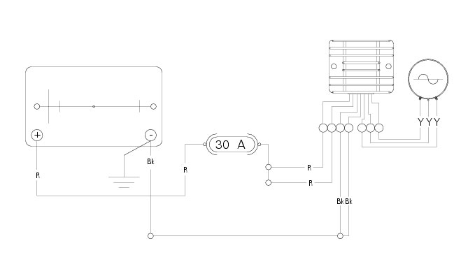
Battery charging system
Checking the battery charging system
To check the current flow in the charging circuit, use the “DDS” tester, which is equipped with an inductive clamp-type amper
emeter.
Follow the instructions given in the paragraph “
Testing the battery charging system
” (Sect. D 5).
A negative value means that charging system is not powering the loads and a significant amount of current must be supplied by
the battery, which is discharging at the time of the measurement.
Or it is possible to use a multimeter (Sect. P 9,
Diagnostic instruments
): connect the multimeter probes to the battery terminals, select the DC scale on the instrument and check for the presence of 14.5 V ±0.5 at an engine speed of 3000 rpm.
Important
If polarity is reversed when clamping the ammeter onto the cable, the sign of the readings will also be reversed, giving rise to
incorrect diagnosis.
Recharging the battery
Examine the label on the battery showing the check intervals in order to determine when to test the voltage.
Charge the battery if the open circuit voltage is lower than
12.8
V. Leaving the battery discharged for more than one month could damage it. Check the battery charge with a voltmeter.
Always check the condition of the battery before recharging and 1 to 2
hours afterwards.
Important
Pay careful attention to recharging times. Stop charging immediately if the battery becomes too hot to the touch. Leave to cool
before resuming charging.
Use only constant-voltage battery chargers.
Check that battery terminals are properly connected to the battery charger.
For recharging, follow the instructions on the battery; for further details consult the table below.
Type of charging
Volt.
Ampere (A)
Time (Hours)
Normal
12
1.2
5-10
Fast
12
5.0
1
Use fast charging in emergencies only.
Storing the battery
If the battery voltage is less than or equal to 11.5
V, it must be recharged.
Connect the battery charger to the battery.
Use a voltage of 16-17
V.
If the ammeter shows no change, increase the voltage to the maximum of 25
V.
Charge for 5
minutes.
If the ammeter shows a change, return the voltage to 16-17
V; otherwise replace the battery.
Topping up the electrolyte
Remove the battery from the motorcycle.
Warning
Before carrying out any operations on the battery, keep in mind the safety standards (Sect.
A 3,
General safety rules
).
The electrolyte in the battery is toxic and can cause burns if it comes into contact with the skin because it contains sulphuric acid.
Wear protective clothing, a face-mask and goggles when adding electrolyte.
If the liquid comes into contact with the skin, wash thoroughly with cold water. If it comes into contact with the eyes,
wash thoroughly with water for 15 minutes and consult an ophthalmologist. In the event of accidental ingestion, drink large quantities of water or milk, and continue with milk of magnesia, beaten egg or vegetable oil. Do not allow sparks, flames, cigarettes or any other heat source to come near the battery, as it produces explosive gases.
When recharging or using the battery indoors, make sure that the room is adequately ventilated. Do not inhale the gases pro
duced during recharging.
KEEP OUT OF REACH OF CHILDREN.
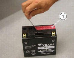
Place the battery on a flat surface.
Remove the protective film (1).
Warning
Make certain that the electrolyte is of the specific type for your battery.
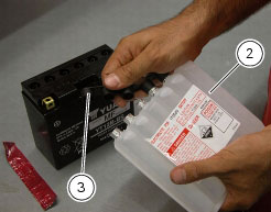
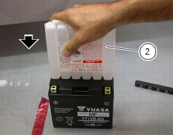
Remove the container with the electrolyte from the plastic bag.
Remove the cap strip (3) from the container (2).
Important
Keep the cap strip (3) to hand because it will be used later as plugs for the battery cells.
Warning
Do not peel or perforate the sealed areas.
Place the electrolyte container (2) upside down. Align the six sealed elements with the six filler holes on the battery.
Push the container (2) downwards with sufficient force to break the seals and allow the liquid to flow out.
Note
Do not tilt the electrolyte container as this could interrupt the flow temporarily or even permanently.
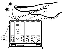
Make certain that air bubbles emerge from all six filler holes. Leave the container in this position for at least twenty minutes. If
no bubbles emerge from one of the holes, tap gently on the bottom of the respective container.
Important
Never move the container away from the battery. Do not cut or puncture the liquid container.
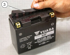
Make sure that all the electrolyte has flowed out. Carefully extract the container (2) from the battery.
Place the sealing cap strip (3) previously removed from the electrolyte container (2) on the battery, taking care not to force it into
the filler holes.
For 3-12
Ah batteries, leave to stand for at least 30 min.
For batteries of over 12
Ah, leave to stand for at least 1 hour.
Note
If using an automatic charge reducing battery charger, make certain that the charger current (amps) is greater than or equal to
the standard (STD) recharging system indicated on the battery.
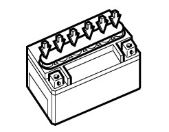
Press down firmly with both hands until the caps are firmly in place (do not use a hammer).
Battery
Safety rules
Warning
Before carrying out any operations on the battery, keep in mind the safety standards (Sect.
A 3,
General safety rules
).
When under charge, batteries produce explosive gases. Keep batteries away from heat sources, sparks or open flames.
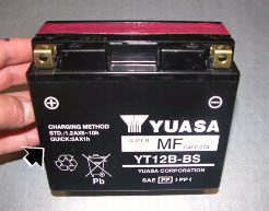
Instructions for use
The battery is a sealed, maintenance-free type and therefore requires no servicing installation.
Note
Always keep the battery clean. Apply grease around the battery terminal clamps to prevent corrosion.
Warning
Never remove the retainer bar (1) on the top of the cover or add more liquid to the battery. If the casing, the cover or the terminals
are broken, or if the sealing cap strip has been tampered with, the battery must be renewed.
Important
If the motorcycle is left unused for more than 30 days, remove the battery and store it in a safe, cool place.
Always charge the battery before the first use and after long storage periods - such as before selling the vehicle.
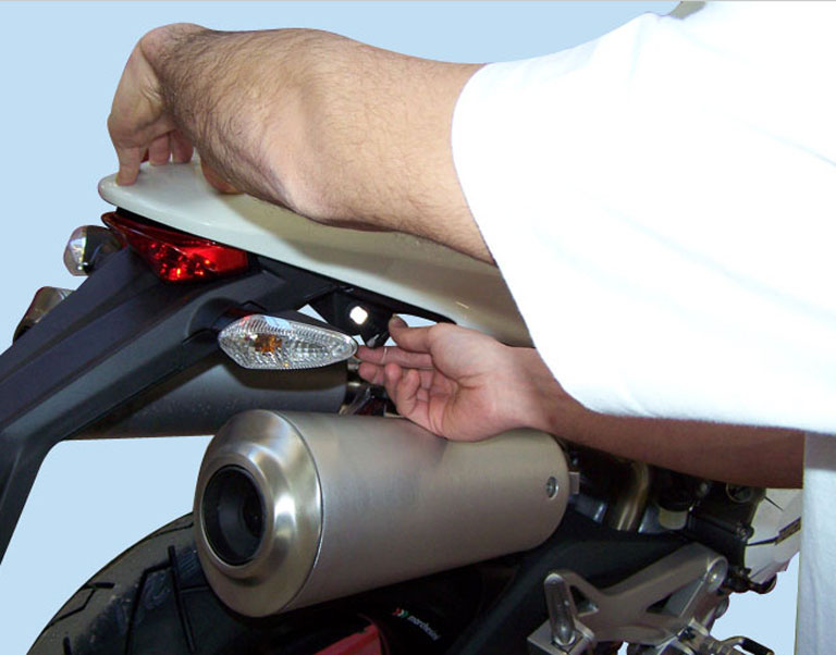
Removal of the battery
Insert the key in the lock and simultaneously apply downward pressure in the area of the catch to release the pin.
Pull the seat backwards to release it from the front catches and remove it from the frame.
Remove the tank covers (Sect.
E 2,
Removal of the fuel tank fairings
).
Remove the fuel tank (Sect.
L 2,
Removal of the fuel tank
).
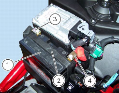
Remove the elastic retaining strap (2) and slide out the battery (1).
Remove the caps from the terminals, unscrew the screws (3) and (4) on terminal clamps always starting from the negative one
(3).
Refitting the battery
Install the battery (1) in the battery support and secure it with the elastic retaining strap (2).
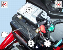
Warning
Connect the positive lead (4) to the positive terminal and the negative lead (3) to the negative terminal, as shown in the photo.
Insert the screws in the terminals (3) and (4), always starting with the positive terminal (red lead) (4).
Warning
Position the leads (3) and (4) as shown in the photo.
Tighten the terminal clamp screws to the specified torque (Sect.
C 3,
Frame torque settings
) and apply grease around the battery terminals to prevent oxidation.
Fit the protective caps to the battery terminals.
Refit the remaining parts in the reverse order with respect to disassembly.
Battery support
Remove the battery, as previously described in the paragraph “
Battery
“ of this section.
Remove the vertical head coil as described in Sect.
M 3,
Coil
.
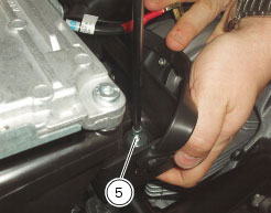
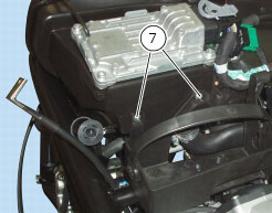
Unscrew the screws (7) and screw (5) and remove the battery support from the airbox.
Refit all the removed parts in the reverse order to that in which they were removed, paying attention to screw tightening torques
(Sect. C 3,
Frame torque settings
).
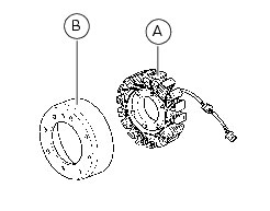
Alternator
It is equipped with a
12
V,
520
W alternator, consisting of a stator (A) located in the generator cover and a rotor (B) fixed to the crankshaft.
Warning
To check the battery charging system for faults, use the DDS diagnosis instrument and follow the instructions given in the para
graph, “
Testing the battery charging system
“ (Sect. D 5).
The absolute value of voltage measured across the terminals of two of the three yellow cables (the measured value will be the
same whichever combination of cable is used) must be within the range indicated in the table below.
(Ambient temperature:
20
°C)
Important
Before testing, disconnect the alternator wiring from the electric system when the ignition key is set to OFF.
Engine rpm
2000
6000
V
effective
27
±
10
78
±
10
Values significantly lower than those indicated above can be due to:
-
partially demagnetised rotor;
-
short-circuited windings.
In the above cases the whole alternator assembly (rotor and stator) should be renewed.
If checks have a favourable outcome, reconnect the alternator to the regulator with ignition key on OFF. Make sure that no cables
are damaged or disconnected.
Removal of the alternator
Disconnect the cables of the generator-side electric system (refer to the chapter “
Routing of wiring on frame
”, Sect. P 1).
Operation
Section reference
Drain the engine oil
D
4,
Changing the engine oil and filter cartridge
Remove the gearchange control
F
5,
Removal of the gearchange control
Remove the clutch slave cylinder
F
2,
Removal of the clutch slave cylinder
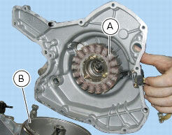
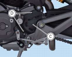
Undo the screws (D) and remove the sprocket cover (C).
Remove the generator cover, the stator (A) and the rotor (B) (Sect.
N 8,
Removal of the generator cover
).
Refitting the generator
Install the rotor (B), the stator (A) and the generator cover (Sect.
N 8,
Refitting the generator cover
).
Fit the sprocket cover (C) tightening the screws (D) to the specified torque (Sect. C
3,
Frame torque settings
).
Operation
Section reference
Refit the clutch slave cylinder
F
2,
Refitting the clutch slave cylinder
Refit the gearchange control
F
5,
Refitting the gearchange mechanism
Top up the engine oil
D
4,
Changing the engine oil and filter cartridge
Connect the cables of the alternator-side electric system (refer to the table in chapter “
Routing of wiring on frame
”, Sect. P 1).
Rectifier-regulator
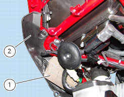
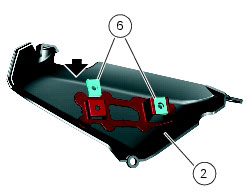
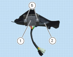
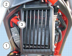
The regulator (1) is fixed to the RH air scoop (2).
The rectifier/regulator consists of an aluminium casing containing the diodes that rectify the current produced by the alternator.
It also contains an electronic device that regulates the current supplied by the alternator in accordance with battery voltage.
If
the battery is drained, the current has the value necessary to restore optimum operating conditions of the battery.
In contrast, if the battery is fully charged, the current value will be lower.
Note
Check the charging current using the DDS diagnosis instrument following the instructions given in the paragraph “
Testing the battery charging system
” (Sect. D 5).
Removal of the regulator
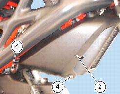
Loosen the retaining screws (3) and (4) and remove the right-hand conveyor (2) from the frame, together with regulator (1).
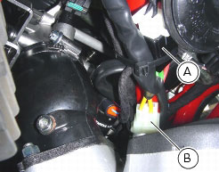
Disconnect connector (B) from generator and main wiring harness (A) (Sect.
P 1,
Routing of wiring on frame
).
Remove the regulator (1) from the RH air scoop (2) by unscrewing the two screws (5).
Important
Do not disconnect the battery cables when engine is running because this would cause irreparable damage to the regulator.
Refitting the regulator
Check that the two threaded clips (6) are installed on the RH air scoop (2) and positioning as shown in the figure.
Fix the regulator (1) to the RH air scoop (2) with the two screws (5).
Tighten the screws (5) to the specified torque (Sect.
C 3,
Frame torque settings
).
Connect the generator connector (B) and main wiring harness (A) (Sect.
P 1,
Routing of wiring on frame
).
Note
In order to correctly route regulator cable, indicated with reference numbers (25) and (26), follow instructions given in Tables E
and H under “
Routing of wiring on frame
”, Sect. P 1.
Refit the right-hand conveyor (2) together with regulator (1) to frame, then tighten
the screws (3) and (4) to the specified torque (Sect. C 3,
Frame torque settings
).
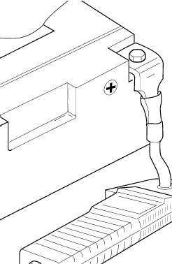
Regulator fuse
The
30
A fuse (1) located on the airbox protects the electronic regulator.
A blown fuse can be identified by breakage of the inner filament (B)
To gain access to fuse, proceed as follows: remove the seat, so insert the key in the lock and simultaneously apply downward
pressure in the area of the catch to release the pin.
Pull the seat backwards to release it from the front catches and remove it from the frame.
Remove the tank covers (Sect.
E 2,
Removal of the fuel tank fairings
).
Remove the fuel tank (Sect.
L 2,
Removal of the fuel tank
).
A blown fuse can be identified by breakage of the inner filament (B)
Important
Switch the ignition key to
OFF
before replacing a fuse to avoid possible short circuits.
Warning
Never use a fuse with a rating other than the specified value. Failure to observe this rule may damage the electric system or even
cause fire.
Refitting is the reverse of removal.
P