8 -
1
2
3
4
5
6
7
8
9
10
11
12
13
14
15
16
17
18
19
20
21
22
23
24
25
26
27
28
29
30
31
32
33
34
35
36
37
38
39
40
41
42
43
44
45
46
47
 Spare parts catalogue
Important
Bold reference numbers in this section identify parts not shown in the figures alongside the text, but which can be found in the exploded view diagram.
Operating principle of the catalytic converter
This model is fitted with “three-way” catalytic converters. Catalytic converters are fitted to the exhaust system in order to elim­inate the noxious substances found in exhaust fumes, namely CO (carbon monoxide), HC (unburnt hydrocarbons) and NOx (nitric oxide). The catalytic converter has a special honeycomb support, coated with aluminium oxide, which creates an irregular surface thus increasing the surface area exposed to exhaust gas. The aluminium oxide is coated with activated substances that help to remove harmful components of exhaust emissions. These substances are usually platinum and rhodium. Platinum allows the oxidation (combination with oxygen) of CO and HC. Rhodium allows the reduction (combination with CO) of NOx contents.
To ensure that CO and HC components can oxidise to form water and carbon dioxide and that NOx contents can be reduced by forming nitrogen and carbon dioxide, there must be a precise amount of oxygen in the exhaust gas. For this reason it is essential that the air-fuel mixture is correctly proportioned. This result has been achieved thanks to the use of a sophisticated fuel system designed to meter the air-fuel mixture with absolute precision.
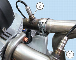
The lambda sensor (Sect. M 3) monitors the oxygen content of exhaust fumes and transmits the relative data instantaneously to the ECU. The control unit (through injection) keeps the air-fuel ratio as close as possible to optimum value (with a certain toler­ance) in order to ensure top performance of the catalytic converters in the exhaust pipes. In terms of emissions, this means achieving minimum hydrocarbon (HC) and carbon monoxide (CO) emissions as well as minimum nitrogen oxide (NOX) emissions. The 3 way catalytic converters complete the exhaust fumes cleaning process by converting residues of CO, HC and NOX in the exhaust gas, thus ensuring exhaust emissions comply with EURO 3 regulations.
How to ensure that the catalytic converter functions correctly
In order to function correctly, the catalytic converter must reach a temperature of around 800 °C and never fall below 300 °C. The indicated maximum temperature must not be exceeded, otherwise the catalytic converter could be irreparably damaged. For this reason, it is essential that significant quantities of unburnt fuel do not accumulate in the exhaust gas post-treatment el­ement, since these would otherwise burn resulting in a sharp increase in temperature. This is why the ignition-injection system should always be in perfect working order (misfiring is not acceptable). Moreover, never push-start the motorcycle (with key and ENGINE STOP button set to ON). In this instance, if the engine does not start, any unburnt fuel would enter the exhaust system and stay in the catalytic converters. Motorcycles fitted with catalytic converters must be used exclusively with unleaded petrol. Otherwise the lead content of petrol would deposit on the activated substances and limit their action against the harmful com­ponents of exhaust gas.
Removal of the exhaust system
Remove the retaining spring (10) of the LH silencer (8) from the centre exhaust pipe (5).
While holding the nut (31), unscrew the retaining screw (30) and remove the LH silencer (8) from the motorcycle.
Recover the spacer (23) and the rubber bushes (24).
Remove the left-hand side heat shield (33) loosening screws (26), (42) and (41); recover the spacers (45), (44) and the washers (34).
Follow the same procedure to remove the RH silencer (7).
Remove the protection (35), unscrewing the screw (26) and recovering the washers (34) and corresponding spacer (25).
Remove the circlip (A) from cable (36) of the exhaust valve (B).
Remove the cable (36) from the exhaust valve (B).
Loosen the screws (15), keeping washers (38), to remove the exhaust valve motor (37) from the rear protection plate and discon­nect wiring (D).
Remove cable (36) from exhaust valve motor (37) sliding out pawl (C) from its seat.
Loosen the two nuts (20) and take central exhaust pipe (5) off the mounting bracket for tank and exhaust (E).
Disconnect the two lambda sensors (2) from the main wiring harness (Sect. P 1, Routing of wiring on frame). Refer to Section M 3, Lambda sensor for details on lambda sensor.
Unscrew the screw (15) retaining the central exhaust pipe (5) to engine and remove the bottom plate (6).
Unscrew the clamp (16) and separate the centre exhaust pipe (5) from the horizontal cylinder exhaust pipe (3) and the vertical cylinder exhaust pipe (4).
Loosen and remove the nuts (9) fastening the exhaust pipe flanges (3) and (4) to the cylinder heads.
Remove the flanges from the cylinder heads.
Slide out horizontal exhaust pipe (3) from vertical head; recover the gasket (1).
Remove the vertical exhaust pipe (4) from the vertical cylinder head, recovering the gasket (1).
Important
Block off the exhaust ports on the head to prevent foreign matter from entering the combustion chamber.
Undo the screws (26) and remove the horizontal heat shield (13); recover the spacers (25) and the washers (34).
Refitting the exhaust system
Renew the gaskets (1).
Refit the horizontal cylinder exhaust pipe (3) and the vertical cylinder exhaust pipe (4) to the respective cylinder heads.
Tighten the nuts (9) fastening the flanges to the heads to the specified torque (Sect. C 3, Frame torque settings).
Check that the quick-release fasteners (32) are installed on the horizontal cylinder exhaust pipe (3).
Refit the horizontal heat shield (13) securing it with the retaining screws (26), the spacers (25) and the washers (34).
Tighten the screws (26) to the specified torque (Sect. C 3, Frame torque settings).
Engage the rear ABS sensor connector (C) to lower plate (6).
Fasten the vertical head exhaust pipe (5) to engine and tighten screw (15) to the specified torque (Sect. C 3, Frame torque set­tings).
Insert the centre exhaust pipe (5) in the horizontal cylinder exhaust pipe (3) and vertical cylinder exhaust pipe (4) and secure with the clamps (16).
Position the clamps (16) as shown in the figure.
 
Position the clamps (16) so they are flush with the end of the exhaust pipes, or at least so that the notches (B) are not completely uncovered.
Tighten the clamps (16) to the specified torque (Sect. C 3, Frame torque settings).
Refit cable (36) to exhaust valve motor (37) fitting pawl (C) in its seat.
Connect the wiring (D) to the main wiring harness (Sect. P 1, Routing of wiring on frame).
Refit the cable (36) to the exhaust valve (B).
Adjust cable (36) on exhaust valve and exhaust valve motor as explained under Sect. D 4, Adjusting the exhaust valve bowden cable.
Refit the circlip (A) to cable (36) of the exhaust valve (B).
Set the exhaust valve motor (37) onto rear protection plate, paying attention to position the spring (F) as shown. Insert the fixing screws (15) with washers (38). Tighten the screws (15) to the specified torque (Sect. C 3, Frame torque settings).
Fasten wiring (D) to exhaust valve motor central body using the rubber tie (39) and ensuring that the cables coming out of motor do not touch the metal sheet sharp edge.
Refit the protection (35), starting the screw (26) with washers (34) and corresponding spacer (25).
Note
When installing the protection (35), ensure that slot (G) matches the tab (H), as shown below.
Fasten the central exhaust pipe (5) to the mounting bracket of tank and exhaust (E) tightening nuts (20) to the specified torque (Sect. C 3, Frame torque settings).
 
Connect the lambda sensors (2) to the main wiring harness (Sect. P 1, Routing of wiring on frame).
Connect the silencer (8) to the centre exhaust pipe (5) and locate the springs (10).
If removed, install the two rubber bushes (24), positioning on either side of the silencer bracket (27).
Insert the spacer (23) in the silencer support bracket (27).
Move the silencer support brackets so that they rest against the footrest brackets (A).
Insert the screw (30) and, on the opposite side, fit the nut (31).
Tighten the screw (30) to the specified torque (Sect. C 3, Frame torque settings) while holding nut (30).
Check that the quick-release fasteners (32) are installed on the LH silencer (8).
Fit the left-hand side heat shield (33) and install, in-between heat shield and exhaust silencer (8), the three washers (34) and spac­ers (44) (25) and (45), as shown below.
Start the screws (42), (26) and (41) in their thread with washers (34) onto left-hand side heat shield (33).
Tighten the screws (42), (26) and (41) to the specified torque (Sect. C 3, Frame torque settings).
 
Follow the same procedure to refit the RH silencer (7).