3 -
Electronic Control Unit (ECU)
The engine ECU (1) is an electronic digital microprocessor-based unit.
It controls both the injectors and the coils, thus controlling fuel injection and ignition in accordance with the engine operating conditions detected by the following sensors:
-
-
-
-
-
The ECU also monitors battery voltage so that it can adjust injector opening time and ignition coil charging time accordingly.
The ECU determines the following values:
-
-
-
Important
The maps, which include ignition advance values, injection times, crankshaft angle for injector closing and all correction curves as a function of temperature and atmospheric pressure values, are stored in the Flash Eprom of the ECU. The above values are preset by the Manufacturer after testing the motorcycle under different riding conditions.
These settings cannot be changed.
Removal of the electronic control unit
To remove the ECU (1) it is necessary to remove the fuel tank (Sect. L 2, Removal of the fuel tank), disconnect ECU connector (2) and undo the retaining screws (3).
Refitting the electronic control unit
Fix the ECU (1) to the airbox with the fours screws (3) and reconnect the wiring connector (2).
Tighten the screws (3) to the specified torque (Sect. C 3, Engine torque settings).
The connector (2) is 48 PIN connector.
Make sure that the clip (A) for the connector (2) is in its “open” position (as shown in the diagram).
Rotate the clip (A) to secure the connector (clip in “locked” position).
Refit all the removed parts in the reverse order to that in which they were removed.
Fuel injectors
The injectors (1) deliver the correct quantity of fuel required for optimal engine operation.
The ECU controls injector opening by feeding current to the coil of an electromagnet which creates a magnetic field to attract the armature, thereby generating fuel spray. If we take the physical characteristics of the fuel to be constant (viscosity, density), as well as the injector delivery and pressure head (controlled by the fuel pressure regulator), the amount of fuel injected depends on the duration for which the injector is open. This time is determined by the ECU in accordance with the engine operating conditions. In this way correct fuel delivery in ensured.
To remove and refit the injectors, refer to Sect. L 6, Removal of the fuel injectors.
Note
To check correct operation of the injector, use the DDS diagnosis instrument and follow the instructions given in the paragraph “Guided diagnosis“ (Sect. D 5).
 
The fuel output must be even and the jet should be fully atomised, without droplets.
Do not leave the engine stopped for a long time with the fuel circuit full. The fuel could clog the injectors and render them inop­erable. Periodically, after lengthy periods without running the engine, we recommend adding TUNAP 231 to the fuel in the tank to help clean critical sections of the fuel circuit.
Stepper motor
The throttle body incorporates an automatic choke function performed by a stepper motor (1).
The stepper motor shaft is fitted with a valve which opens a communicating passage between two ports; one of these ports (2) is connected to the intake manifold of the vertical cylinder while the other (4) is connected to the intake manifold of the horizontal cylinder. A third port (3) is connected to the airbox.
The stepper motor simultaneously controls two by-pass ports having an air flow capacity of around 6 kg/h.
The by-pass ports with adjuster screws are present because it is necessary to balance the air flow to the two cylinders.
In order to compensate for the quantity of supplementary air supplied by the stepper motor and consequently deliver the correct amount of fuel, the ECU converts the stepper motor steps into angular degrees of the throttle: this system means that opening the stepper motor is equivalent to opening the throttle.
Note
The influence of the stepper motor air flow is present to approximately 30° throttle angle; no correction is required for greater angles.
 
The opening of the stepper motor opening is controlled by 2 strategies:
Strategy 1) controlled solely by engine temperature (stepper motor opening/closing is determined by engine temperature alone).
Strategy 2) controlled by engine temperature and status. This strategy is applied only in the engine starting phase; the system determines a quantity of steps, to be added to those of the previous strategy, which are immediately decreased to zero, in accordance with the number of engine cycles, once the system has detected that the engine has started.
Lambda sensor
The Lambda sensor, positioned on the exhaust pipe, transmits information to the ECU on the amount of oxygen present in the exhaust fumes. With this information the ECU can maintain optimal control over the fuel‑air mixture.
The outer surface of the sensor element in zirconium dioxide is in direct contact with the exhaust gas, while the inner surface is in contact with the atmosphere. Both surfaces are coated with a thin layer of platinum. Oxygen in ionic form travels through the ceramic layer and charges the platinum layer electrostatically so that the platinum acts as an electrode: the electrical signal gen­erated is carried on the sensor output cable.
The zirconium dioxide element becomes permeable to oxygen ions at a temperature of around 300 °C.
When the oxygen concentration is different on the two sensor surfaces, a voltage is generated thanks to the special physical properties of the zirconium dioxide. With a lean mixture the signal voltage is low, while with a rich mixture it is high.
The typical change in signal intensity occurs when the air-fuel ratio is 14.7 to 1 (14.7 parts of air to 1 part of petrol), which is referred to as “Lambda 1”. This ratio is considered to be an indication of complete combustion, hence the name “Lambda Sensor”: hence
lambda = 1 means mixture in stoichiometric ratio
lambda >1 means a lean mixture
lambda <1 means a rich mixture.
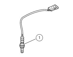
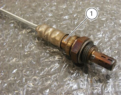
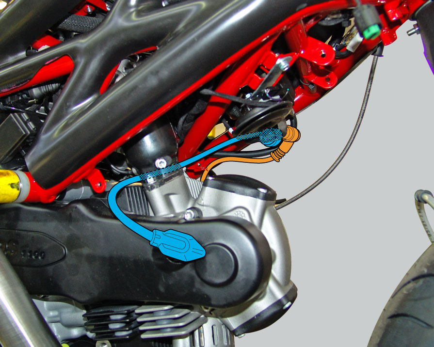
The air-fuel ratio control system is managed by the lambda sensor, which starts to operate at over 300 °C: the ceramic material starts conducting oxygen ions at around 300 °C. If the proportion of oxygen starts to differ between the two ends of the probe, this generates an electrical voltage between the two electrodes due to the particular nature of the material. This makes it possible to measure the difference in oxygen content between the exhaust gas and the ambient air. Combusted gas still contains a resid­ual amount of oxygen when the air-fuel mixture delivered to the combustion chamber is incorrect. This makes it possible to adjust the injection control unit to ensure the engine always runs with the optimal air-fuel ratio.
To remove the lambda sensors (1) it is necessary to unscrew them from the horizontal and vertical cylinder exhaust pipe.
When refitting, tighten the sensors to the specified torque (Sect. C 3, Frame torque settings).
Air pressure sensor
This sensor is powered by the ECU and it supplies information concerning the absolute air pressure in an area of the motorcycle that is not subject to turbulence. The electronic signals thus obtained are transmitted to the ECU, where they are used to make corrections in accordance with the detected pressure.
Note
To test the operation of the injector, use the DDS diagnosis instrument and follow the instructions given in the paragraph “Guided diagnosis” (Sect. D 5).
Removing the air pressure sensor
To remove the air pressure sensor (1), remove the following parts.
 
Disconnect the main wiring connector (3) from the sensor and detach it from the throttle body.
Remove the tubes (2) from the intake manifolds.
Refitting the air pressure sensor
Refitting is the reverse of removal.
On completion of the refitting operation, reconnect the wiring connector (3) to the sensor.
 
Temperature sensor
This sensor is powered by the ECU and provides information regarding the temperature of the aspirated air.
The electronic signals thus obtained are transmitted to the ECU, where they are used to make corrections in accordance with the temperature reading.
Note
To test the operation of the injector, use the DDS diagnosis instrument and follow the instructions given in the paragraph “Guided diagnosis” (Sect. D 5).
Removing the air temperature sensor
To remove the air temperature/pressure sensor (1), remove the following parts.
 
Disconnect the main wiring connector (1) from the sensor, unscrew and remove the two sensor retaining screws (2) and remove the sensor from the vertical cylinder intake manifold (3).
Refitting the air temperature sensor
Refitting is the reverse of removal.
On completion of the refitting operation, reconnect the wiring connector to the sensor (1).
 
 
Spark plug
Clean the area around the spark plug bores with a compressed air jet before removing the spark plugs themselves.
Remove the spark plug caps (1) from the spark plugs in both cylinder heads and remove the two spark plugs, making sure that no dirt or other objects enter the combustion chamber.
Important
Check the gap between the central and side electrodes.
If the gap is not as specified or if the spark plug is soiled with heavy sooty deposits, renew it.
 
Refit the spark plug in the cylinder head, first tightening it fully by hand.
Tighten it to the specified torque (Sect. C 3, Frame torque settings).
Refit the spark plug caps (1).
Important
Do not use spark plugs with inadequate thermal rating or incorrect thread length. The spark plug must be securely installed.
If a spark plug is loose, it can overheat and damage the engine.
 
Spark plug type:
Make: CHAMPION
Type: RA6HC
Alternative:
Make: NGK
Type: DCPR8E
 
Coil
An inductive discharge ignition system is used. Coil operation is governed by the M3C electronic control unit, which calculates the ignition advance. The power module (integrated in the electronic control unit) also guarantees constant energy coil charge, by adjusting the dwell time.
The horizontal head coil (1) is mounted under the airbox so that to remove it you shall first remove the left-hand side conveyor cover (Sect. P 3, Starter contactor).
The vertical head coil (2) is on the battery mount, so that to remove it, you shall:
Remove the seat (Sect. E 3, Removal of the seat).
Remove the tank covers (Sect. E 2, Removal of the fuel tank fairings).
Remove the fuel tank (Sect. L 2, Removal of the fuel tank).
To remove coil (1), disconnect spark plug cables (3).
Remove the screws (4) collecting spacers (7).
Remove the coil (1) from the airbox.
To remove coil (2), disconnect spark plug cables (6), remove the screws (4), paying attention to the washers.
Remove the coil (2).
Refitting is the reverse of removal; ensure to tighten the screws (4) to the specified torque (Sect. C 3, Frame torque settings).
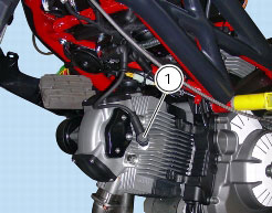
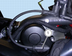
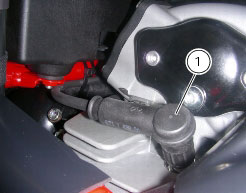
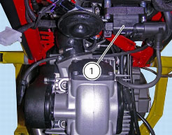
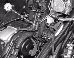
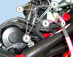
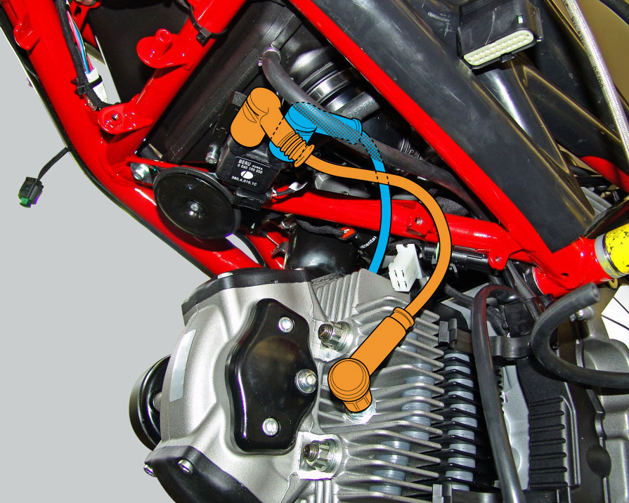
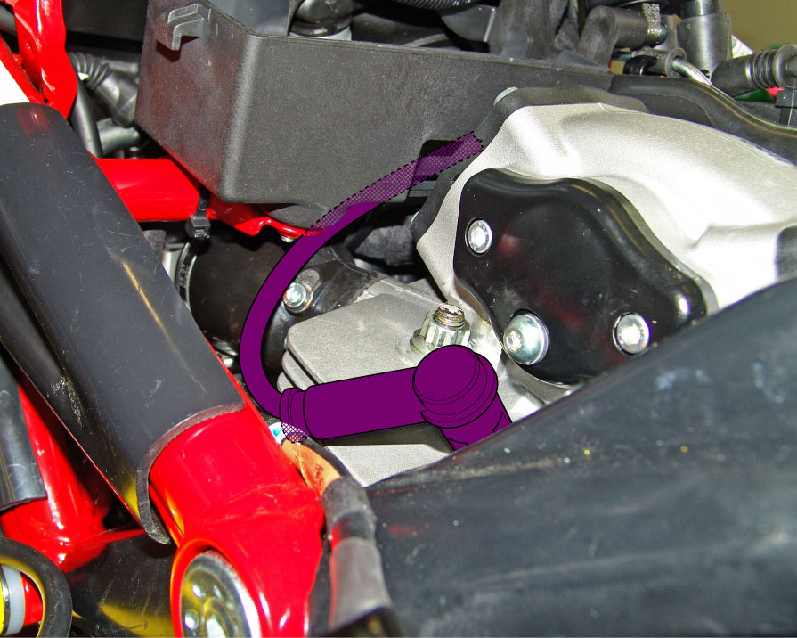
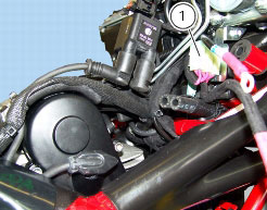
The horizontal cylinder and vertical cylinder coils differ because of the different length of the spark plug cables: the vertical coil (2) has short spark plug cables (6), while the horizontal coil (1) has longer spark plug cables (3).
Position the HT leads (3) and (6) as shown in the following photos.
Refit the left-hand side conveyor (Sect. P 3, Starter contactor).
Refit the fuel tank (Sect. L 2, Refitting the fuel tank).
Refit the tank covers (Sect. E 2, Refitting the fuel tank fairings).
Refit the seat (Sect. E 3, Refitting the seat).
 
Note
To check the coils for faults, use the DDS diagnosis instrument and follow the instructions given in the paragraph “Guided diag­nosis“ (Sect. D 5).
Positioning of the HT leads
 
Throttle Position Sensor (TPS)
The TPS is powered by the ECU to which it sends a signal indicating the throttle position. This information is an indirect measure of the engine load and is used by the ECU as one of the main parameters for defining the fuel flow rate and spark advance.
Note
To check this component, use the DDS diagnosis instrument following the instructions given in the paragraph “Guided diagnosis“ (Sect. D 5).
For throttle position sensor replacement, please refer to Sect. L 6, Removal of the throttle body.
Timing/rpm sensor
This sensor is of the inductive type. it faces the timing gear and is capable of “reading” the 44 teeth and the 2 gaps (each equivalent to 2 teeth) positioned 180° apart.
The signal coming from the pickup on the camshaft gear is used by the ECU to determine the engine speed and as a timing reference point.
Note
To check the elements for faults, use the DDS diagnosis instrument and follow the instructions given in the paragraph “Guided diagnosis“ (Sect. D 5).
 
For instructions on how to renew the sensor and check the air gap, see the chapter “Flywheel - alternator” (Sect. N 8).
Injection and main relay
The relay (1) is positioned alongside the ECU and fixed to the airbox.
To remove the relay, remove the fuel tank (Sect. L 2, Removal of the fuel tank).
Disconnect the relay from the electric system and apply 12 V (battery voltage) between contacts (86) and (85) (small contacts): you should hear a click that confirms that the internal electromagnet has switched.
Connect a multimeter to contacts (30) and (87) (big contacts) to check for electrical continuity (see Sect. P 9, Diagnostic instru­ments, concerning operation of the multimeter). The resistance reading should be near zero and, if present, the continuity sound signal should be emitted. If this does not occur, the part must be renewed.