3 -
Note
The references of the elements listed below are those of the “Wiring diagram”, Sect. P 1.
Electric starting system
The key components of the electric starting system are a contactor (7) and a starter motor (6) fed by the battery (8).
The engine starting strategy is managed entirely by the engine ECU (28), which monitors the following inputs:
-
-
-
-
-
 
When these inputs are combined in the required manner, the engine control unit (28) enables engine starting.
 
The table lists possible engine starting combinations.
In accordance with the status of specific engine control unit inputs and the indications given in the table, the control unit enables operation of the starter motor (ON status) when the START button is pressed.
X = generic status of neutral sensor, clutch, and side stand.
Safety device functions table
Starter motor
Power:
700 W with 12 V power.
Direction of rotation:
counter clockwise viewed from power take-off side.
 
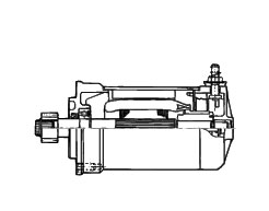
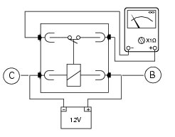
The starter motor is highly compact and reliable and therefore rarely gives any type of problem. In case of malfunction, ensure that the starter motor wiring terminal is properly tightened under the nut and shows no sign of corrosion. If the terminal is properly tightened and free from corrosion, remove the starter motor and test it under no-load conditions (no load applied to the shaft). Secure the starter motor to a test bench, making sure you do not damage the casing. Use a fully charged 12 V battery for the test. Use battery-motor connection cables which are no longer than 70 cm and with the same cross-section as the cable on the motorcycle itself. Connect the negative terminal of the battery to an unpainted area of the starter motor casing and the pos­itive terminal to its electrical terminal. The shaft of the starter motor should rotate freely and at high speed. Take care not to short-circuit the two cables connected to the battery.
Removal of the starter motor
 
Undo the screws (D) and remove the sprocket cover (C).
Remove the generator cover (Sect. N 8, Removal of the generator cover).
Disconnect the starter motor/solenoid cable (3) (see table in the chapter “Routing of wiring on frame”, Sect. P 1).
Unscrew the retaining screws (1).
Note
The starter motor retaining screws are assembled with threadlocker.
 
Slide out the starter motor and gasket (2).
 
Refitting the starter motor
Inspect the condition of the gasket (2) and renew if necessary.
Locate the gasket (2) and the starter motor on the crankcase and tighten the screws (1) to the specified torque (Sect. C 3, Frame torque settings).
Connect the starter motor/contactor cable (3).
Important
Fill the cap with protective grease before fitting it on the starter motor
Refit the generator cover (Sect. N 8, Refitting the generator cover).
Fit the sprocket cover (C) tightening the screws (D) to the specified torque (Sect. C 3, Frame torque settings).
 
Starter contactor
The starter motor contactor (1) is elastically mounted to the airbox.
Disconnect the battery (Sect. P 2, Battery).
To reach the solenoid starter it is necessary to remove the seat, so insert the key in the lock and simultaneously apply downward pressure in the area of the catch to release the pin.
Pull the seat backwards to release it from the front catches and remove it from the frame.
Remove the tank covers (Sect. E 2, Removal of the fuel tank fairings).
Remove the fuel tank (Sect. L 2, Removal of the fuel tank).
Disconnect the wiring connector (10) of the starter contactor from the wiring harness.
Remove the solenoid starter (1) from its housing.
Remove the protective caps (A).
Undo the nuts (6), taking care to collect the spring washers (7).
Remove the starter motor-contactor cable (8).
Remove the contactor-battery cable (9).
Checking operation of the starter solenoid
Apply 12 V (battery voltage) across the positive terminal (B) and negative terminal (C) of the connector.
With a multimeter connected between the two poles (threaded pins (C) and (D) of the solenoid, check for electric continuity (Sect. P 9, Using a multimeter to check the electrical systems). If there is no electrical continuity, renew the solenoid.
 
On refitting, ensure that terminals (C) and (D) are not oxidised.
Connect the wires (8) and (9) to the contactor terminals.
Insert the two bolts (7) and the nuts (6).
Spray suitable protectant onto nuts (6).
Tighten the nuts (6) to the specified torque (Sect. C 3, Frame torque settings).
Install solenoid starter (1) engaging it onto tabs (E), positioning it as shown in the figures.
Refit the wiring connector (10) to the wiring and refit the protective caps (A).
Reconnect the battery (Sect. P 2, Battery).
Refit the remaining parts in the reverse order with respect to disassembly.