|
7 -
|
|
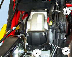
1
|
|
3
|
|
4
|
|
5
|
|
6
|
|
7
|
|
10
|
|
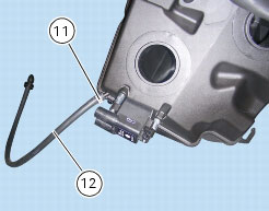
11
|
|
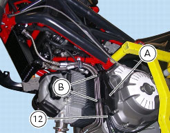
12
|
|
13
|
|
15
|
|
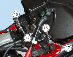
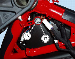
16
|
|
17
|
|
18
|
|
19
|
|
20
|
|
21
|
|
22
|
|
24
|
|
25
|
|
27
|
|
28
|
|
31
|
|
32
|
|
P 2, Battery support
|
|


|
B
|
|
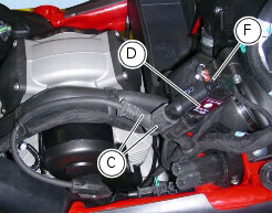
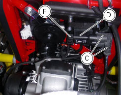
C
|
|
D
|
Coils (Sect. M 3, Coil).
|