4.1 -
1
2
3
4
 Spare parts catalogue
Important
Bold reference numbers in this section identify parts not shown in the figures alongside the text, but which can be found in the exploded view diagram.
Checking and adjusting valve clearances
 
Note
For clarity, the figures show the engine block removed from the frame.
 
Take off the inspection cover on the alternator side and install service tool no. 88713.0123.
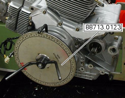
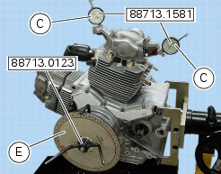
Turn crankshaft with tool no. 88713.0123, and set it so that the horizontal piston is at the TDC in the combustion stage, i.e. the valves of the horizontal head are all at rest position: check the valve clearance on the horizontal cylinder head. Reset the degree wheel of tool no. 88713.0123.
To do the same on the vertical cylinder, turn crankshaft through 270° anticlockwise from current position, i.e. where tool no. 88713.0123 is reset. In this way the vertical piston is at the TDC in the combustion stage, i.e. the valves of the vertical head are all at rest position, and you can now check valve clearance on the vertical head.
Checking the opening clearance (Sa) of the intake/exhaust valves
To check the valve opening clearance (Sa), insert the blade of a feeler gauge between the opening rocker (A) and the shim (3).
Note
While inserting the blade of the feeler gauge to check the clearance, apply gentle leverage to overcome the force of the closing rocker spring and thus eliminate any play in the rocker mechanism: then check that the shim can rotate freely.
 
The clearance values must be within the specified limits (Sect. C 1.1, Timing system/valves).
If not, remove the opening shim (3), as described in chapter “Removal of the rocker arms, shims and valves”, Sect. N 4.4, and replace it with one of suitable height to obtain the prescribed assembly clearance.
Note
Opening rocker arm shims measuring 1.8 to 3.45 are available as replacement parts: the size is punched on the shim.
Checking the closing clearance (Sc) of the intake/exhaust valves
To check the valve closing clearance, insert the blade of a feeler gauge between the closing rocker (B) and the shim (3): the closing clearance (Sc) corresponds to the thickness of the feeler gauge and should allow the free rotation of the shim without any significant play.
The value must be within the prescribed ones (Sect. C 1.1, Timing system/valves).
If not, remove the closing shim (1), as described in chapter “Removal of the rocker arms, shims and valves”, Sect. N 4.4, and replace it with one of suitable height to obtain the prescribed assembly clearance.
Note
Closing rocker arm shims measuring from 2.2 to 4.5 are available as replacement parts: the size is punched on the shim.
Checking valve lift
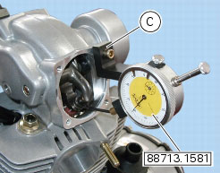
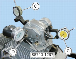
Fit the gauge (C) 88765.1581 in correspondence with the fixing hole of the previously removed cylinder head valve cover, as shown in the photo.
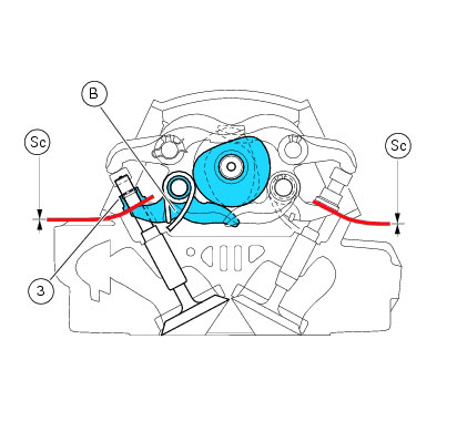
Reset the valve opening clearance when the camshaft is in its rest position by inserting a feeler gauge between the upper rocker arm and the opening shim.
Note
This operation is best done using one dial gauge for the exhaust valve and another one for the intake valve.
 
Make sure the dial gauge fork is centred relative to the valve axis and located against the closing shim.
Set the dial gauge to zero when the valve is fully closed.
Rotate the intake camshaft so as to allow the intake valves to lift fully.
Check on the dial gauge that the measured value corresponds to the prescribed one (Sect. C 1.1, Timing system/valves).
Perform the same procedure for the exhaust valve, fixing the support to the opposite side of the cylinder head.
Remove the tools 88765.1581.
 
Checking the engine timing
Note
Engine timing should be checked after changing parts such as camshafts, valves or timing belt rollers or when overhauling badly worn engines.
 
Remove the spark plugs and install the tool (D) 88765.1297 in the spark plug bore to determine the piston TDC, along with gauges (C) 88713.1581 and the timing check tool with timing degree wheel (E) 88713.0123.
Reset the opening valve clearance when the camshaft is in rest position by inserting a feeler gauge between the opening rocker arm and the opening shim.
Check that in this condition the camshaft can rotate. If it moves stiffly, use a thinner feeler gauge.
In this condition, with the piston of the horizontal cylinder at TDC and the valves fully closed as confirmed by the reading on dial gauge (E), set gauges (C) to zero.
Set the tension value of the belts as described at Sect. D 5, Checking and adjusting timing belt tension.
 
Turn the degree wheel (E) anticlockwise until the gauge dial (C), on the exhaust side, shows a lift of 1 mm. Check that the value of the angular displacement read on the degree wheel (E) is as specified in (Sect. C 1.1, Timing system/valves).
Continue to rotate in the same direction until you obtain a lift of 1 mm on the intake side. Check the angular value on the degree wheel.
Continue to rotate until, in correspondence with the closure of the valve for the compression stroke, you obtain a lift of the intake valve of 1 mm on the gauge (C). Check the angular value with the prescribed one (Sect. C 1.1, Timing system/valves).
Rotate clockwise again until obtaining 1 mm lift of the exhaust valve, on both valve opening and closure.
Check the angular displacement value against the specified value.
Repeat the procedure for the vertical cylinder.
Permissible tolerance for measured values is ±3° with respect to specified values.
Remove the tools used to check engine timing.
 
 
N