|
4
|
|
5
|
|
7
|
|
9
|
|
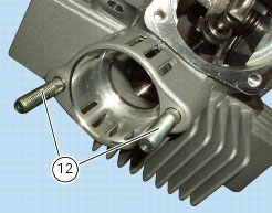
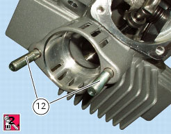
12
|
|
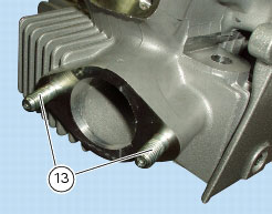
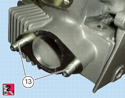
13
|
|
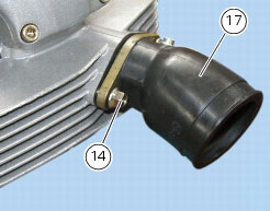
14
|
|
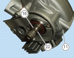
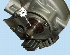
15
|
|
18
|
|
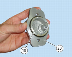
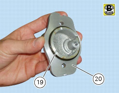
19
|
|
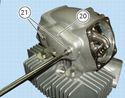
20
|
|
21
|
|
24
|
|
P 2, Battery support
|
|
|
Disconnect ECU connector from main wiring harness
|
|
|
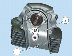
M 3, Spark plug
|
|

|
M 3, Spark plug
|
|
|
P 2, Battery support
|
|
|
M 3, Spark plug
|
|
|
Remove the timing belts and camshaft timing belt pulleys on the heads
|

|
Refit the camshaft timing belt pulleys on the heads and timing belts
|
|
|
M 3, Spark plug
|
|

|
M 3, Spark plug
|
|
|
Remove the timing belts and camshaft timing belt pulleys on the heads
|
|


|
Refit the camshaft timing belt pulleys on the heads and timing belts
|
|
|
M 3, Spark plug
|
|