|
2
|
|
8
|
|
9
|
|
11
|
|
12
|
|
13
|
|
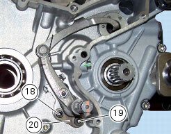
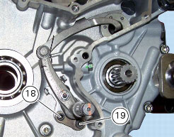
18
|
|
19
|
|
20
|
|
22
|
|
23
|
|
Remove the generator cover and flywheel-generator assembly
|

|
N 6.1, Removal of the clutch
|
|
|
N 2.1, Removal of the oil pump
|
|
|
N 6.1, Reassembling the clutch
|
|
|
Refit the flywheel/generator assembly and generator cover
|
|