|
1
|
|
5
|
|
7
|
|
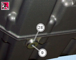
9
|
|
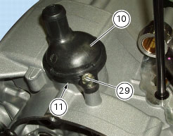
11
|
|
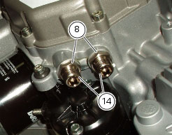
14
|
|
15
|
|
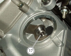
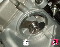
17
|
|
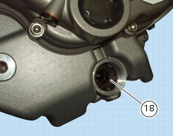
18
|
|
21
|
|
22
|
|
23
|
|
24
|
|
25
|
|
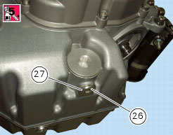
26
|
|
29
|
|
30
|
|
31
|
|
32
|
|
34
|
|
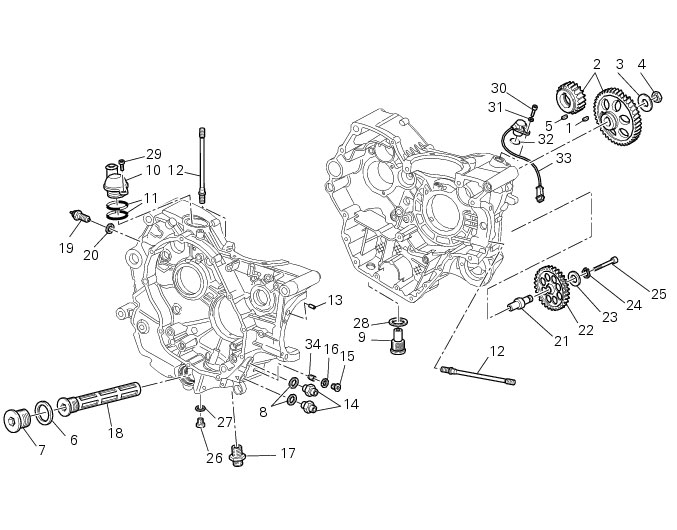
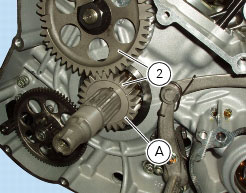
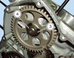
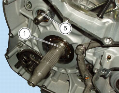
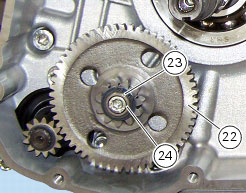
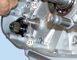
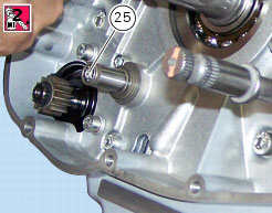
N 2.1, Removal of the oil pump
|
|
|
Remove the timing belts and the timing belt pulleys
|
|
|
Remove the alternator-side crankcase cover and the alternator assembly
|
|


|
Refit the alternator-side crankcase cover and alternator assembly
|
|
|
N 4.3, Refitting the camshafts
|
|
|
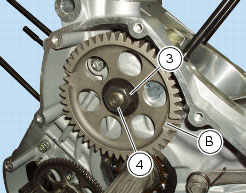
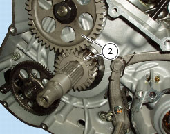
N 2.1, Refitting the oil pump
|
|
|
Remove the generator cover and flywheel-generator assembly
|

|
Refit generator cover and the flywheel/generator assembly
|
|
|
Remove the generator cover and flywheel-generator assembly
|
|
Refit generator cover and the flywheel/generator assembly
|
|