|
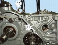
1
|
|
4
|
|
5
|
|
6
|
|
7
|
|
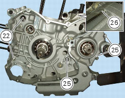
8
|
|
10
|
|
11
|
|
12
|
|
13
|
|
14
|
|
15
|
|
17
|
|
18
|
|
19
|
|
20
|
|
21
|
|
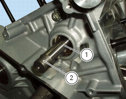
22
|
|
23
|
|
25
|
|
26
|
|
27
|
|
28
|
|
29
|
|
30
|
|
31
|
|
32
|
|
33
|
|
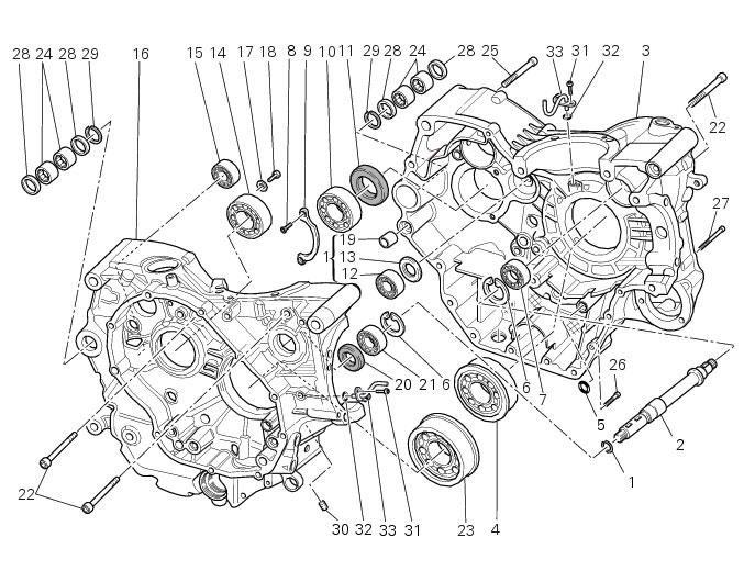
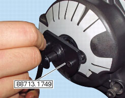
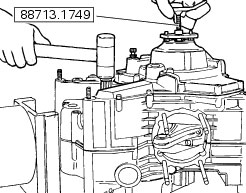
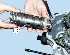
N 2.1, Removal of the oil pump
|
|
|
Remove the timing belts and the timing belt pulleys
|
|
|
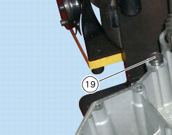
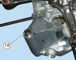
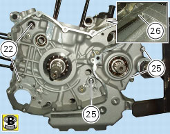
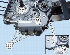
Remove the alternator-side crankcase cover and the alternator assembly
|
|
|
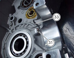
N 6.1, Removal of the clutch
|
|

|
-
|
|
-
|
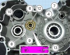
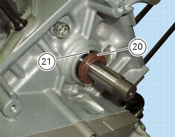
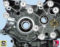
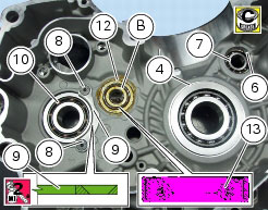
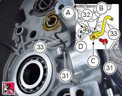
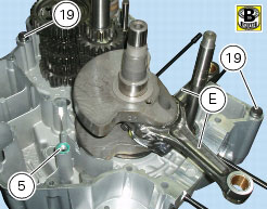
install the new bearing (while the crankcase is still hot) keeping it perfectly square in its seat using a tubular drift that only bears on the outer ring of the bearing;
|
|
-
|
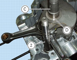
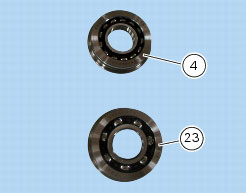
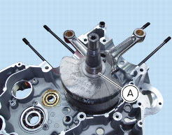
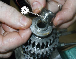
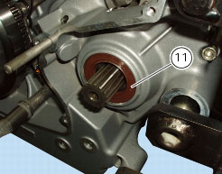
gearbox secondary shaft bearing (15): apply grease to the bearing rollers. Fit the inner race (A) removed previously from the bearing. Apply grease to the inner ring;
|
|
-
|
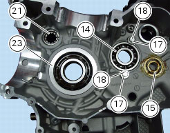
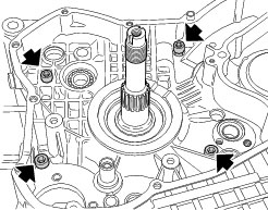
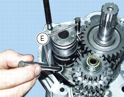
the primary shaft bearing (14), secured with screws (18) and retaining spacer (17): apply prescribed threadlocker to the screws (18) and tighten to the specified torque (Sect. C 3, Engine torque settings);
|
|
Clutch side (mm)
|
Chain side (mm)
|
|
|
Clutch side (mm)
|
Chain side (mm)
|
|
|
M8x90 mm screws
|
||
|
M8x75 mm screws
|
||
|
M6x35 mm screws
|
||
|
M6x75 mm screws
|


|
N 6.1, Reassembling the clutch
|
|
|
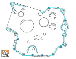
Refit the alternator-side crankcase cover and alternator assembly
|
|
|
N 4.3, Refitting the camshafts
|
|
|
N 2.1, Refitting the oil pump
|
|